Main tee connection

a technology of main tee connection and tee connection, which is applied in the direction of walls, constructions, building components, etc., can solve the problems of hard splice assembly and face misalignment, and achieve the effect of reliable high-strength joint production

Inactive Publication Date: 2006-11-23
USG INTERIORS INC
View PDF23 Cites 16 Cited by
  • Summary
  • Abstract
  • Description
  • Claims
  • Application Information

AI Technical Summary

Benefits of technology

[0003] The invention provides a splice connection for main runners or tees comprising an end assembly with a uniquely formed pocket made in a cavity between the central web of the runner and a separate spring steel clip attached to the web to align and interlock with an identical opposed end assembly. The result is an in-line connection for main runners or tees. Because the disclosed pocket is formed by the cavity created between an embossed recess on one side of the tee web and an inside clip surface, the pocket can be made with a fixed width, regardless of variations in material thickness of the tee itself. The disclosed concept enables a connection to exhibit consistent insertion pressure as a result of the fixed geometry of the tee cavity and the resilient nature of the clip and web assembly.
[0004] The disclosed clip is configured to connect directly with an identical clip so that a reliable high strength joint is produced independent of any variation in the properties of the material of the tee. The clip and pocket are configured to initially self-align the ends of the runners being joined and, when finally connected, to accurately register the butted ends of the runners.

Problems solved by technology

Complaints of hard splice assembly and face misalignment are the result of compromise in ordinary variation in the supply of material, tool wear, and sometimes a lack of constant vigilance at the point of manufacture.

Method used


Image

  • Main tee connection
  • Main tee connection
  • Main tee connection

Examples


Embodiment Construction

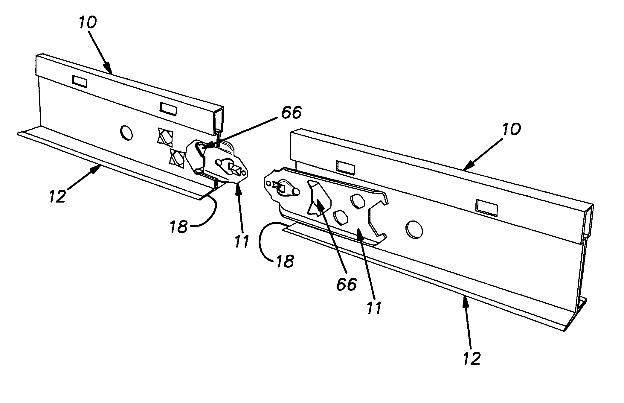
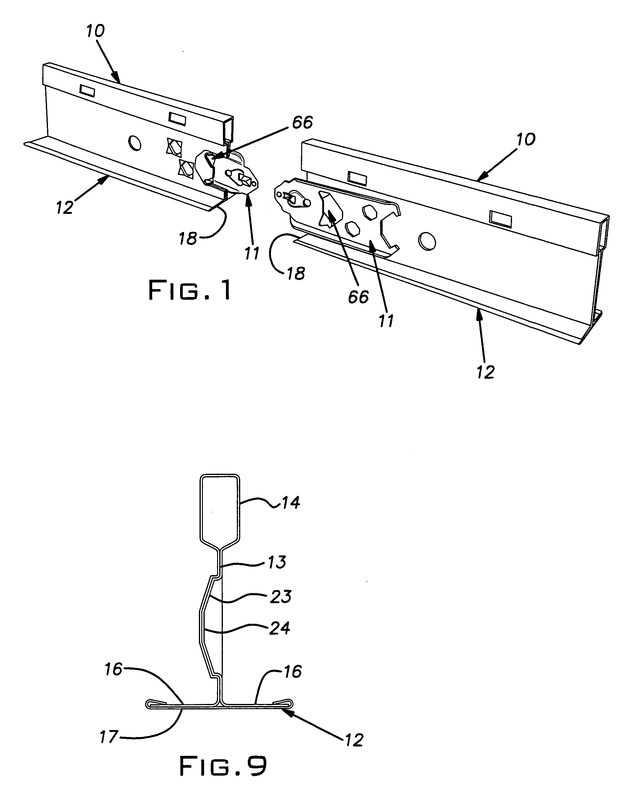
[0017] A main runner or grid tee 10 is assembled at each of its longitudinal ends with a connector clip 11. The illustrated grid tees 10 are generally conventional in construction having a lower flange 12, a web 13 extending vertically upwardly from the center of the flange, and a hollow reinforcing bulb 14 at the upper edge of the web. In a conventional manner, the tee 10 can be made by roll forming continuous strips of mild steel sheet stock so that the bulb 14 has a single wall and the web 13 is formed by two layers of sheet stock and the flange 12 has two portions 16. The flange portions 16 are retained together and concealed from a view below by a cap strip 17 of sheet metal, as is conventional. The roll formed stock is cut into tees of predetermined length, for example, nominally 12 feet. The opposite ends of the tees are cut so that its edges 18 at the flange 12 are perpendicular to the longitudinal direction of the tee and the edges of the web 13 and bulb 14 can be formed in...


PUM


Abstract

A main tee with separate clips affixed on its ends for splicing the tee with identical tees in end-to-end butt joints. The tee and clip form a pocket for receiving the projecting end of an opposing clip with a uniform low insertion force. The clip is self-aligning with the pocket and when interconnected the clips precisely align the coupled tees both vertically and horizontally. The clips, formed of relatively strong material, have mutually engageable locking surfaces that ensure a strong joint.

Description

BACKGROUND OF THE INVENTION [0001] The invention relates to suspended ceiling grid and more particularly, to improvements in splice connections for main runners for such systems. PRIOR ART [0002] Suspended ceiling grid customarily comprises main runners and cross runners that intersect the main runners. The main runners are produced in fixed lengths, typically in 12 foot lengths, and are spliced end-to-end to extend across a room. For connecting their ends, current grid tee or runner products commonly utilize an integral splice or connector cut and formed from the grid runner web material. The splice uses a lanced pocket pushed out from the vertical web plane in one direction and a protruding stiffened tongue with a locking detent pushed out in the opposite direction. Upon installation, the tongue of each runner or tee inserts into an opposing pocket making a double lock. When all of the physical features of the splice are formed in the ideal or desired configuration and location, t...

Claims


Application Information

Patent Timeline
Patent Type & Authority Applications(United States)
IPC IPC(8): E04B9/00
CPCY10T403/57E04B9/10E04B9/00E04B9/06
Inventor LALONDE, PAUL D.LEHANE, JAMES J.COYNE, DANIEL J.
Owner USG INTERIORS INC
Why Eureka
Try Eureka