Pressure-based aircraft fuel capacity monitoring system and method

a fuel capacity monitoring and pressure-based aircraft technology, applied in liquid/fluent solid measurement, machines/engines, instruments, etc., can solve the problems of in-flight explosion or fire, reducing only the severity of the problem, and requiring only the replacement of such wiring located within the fuel tank

Active Publication Date: 2006-11-23
INNOVATIVE SOLUTIONS & SUPPORT
View PDF11 Cites 16 Cited by
  • Summary
  • Abstract
  • Description
  • Claims
  • Application Information

AI Technical Summary

Benefits of technology

[0005] It is accordingly the desideratum of the invention to provide a system and method for dynamically monitoring the amount of fuel rema

Problems solved by technology

These systems require that electrical current-carrying wires connected to the capacitive sensors be located within each fuel tank, with the consequent possibility of a spark that can ignite the fuel vapors and contained fuel and cause an in-flight explosion or fire, as is believed to have occurred in the crash of TWA Flight 800.
Periodic inspection or prophylactic, periodically-scheduled replacement of such wiring located within the fuel tanks is both expensive and largely impractical for comp

Method used


Image

  • Pressure-based aircraft fuel capacity monitoring system and method
  • Pressure-based aircraft fuel capacity monitoring system and method
  • Pressure-based aircraft fuel capacity monitoring system and method

Examples


Embodiment Construction

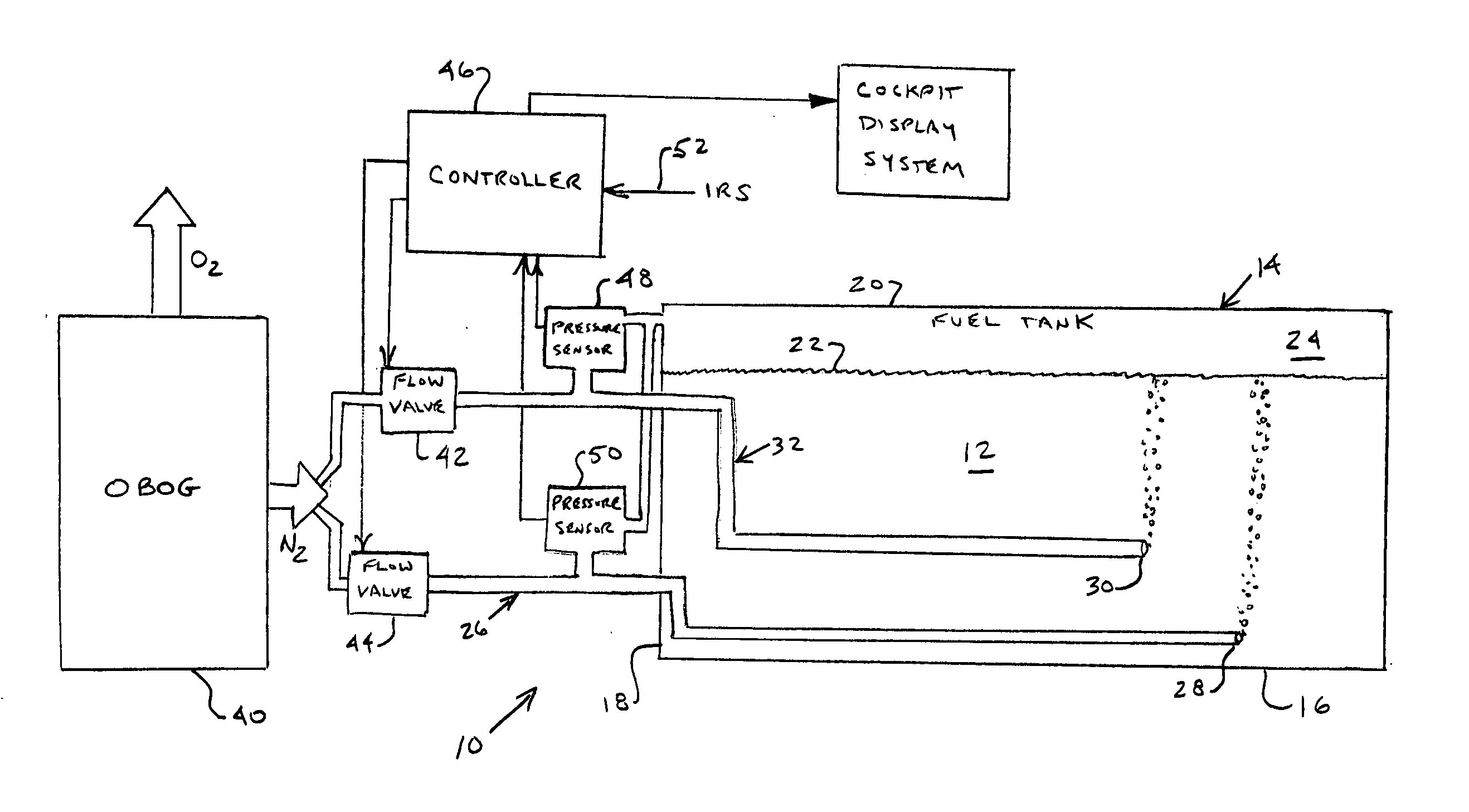
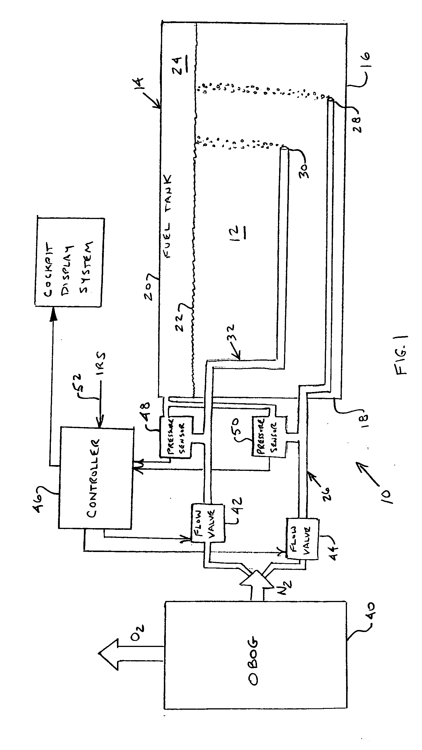
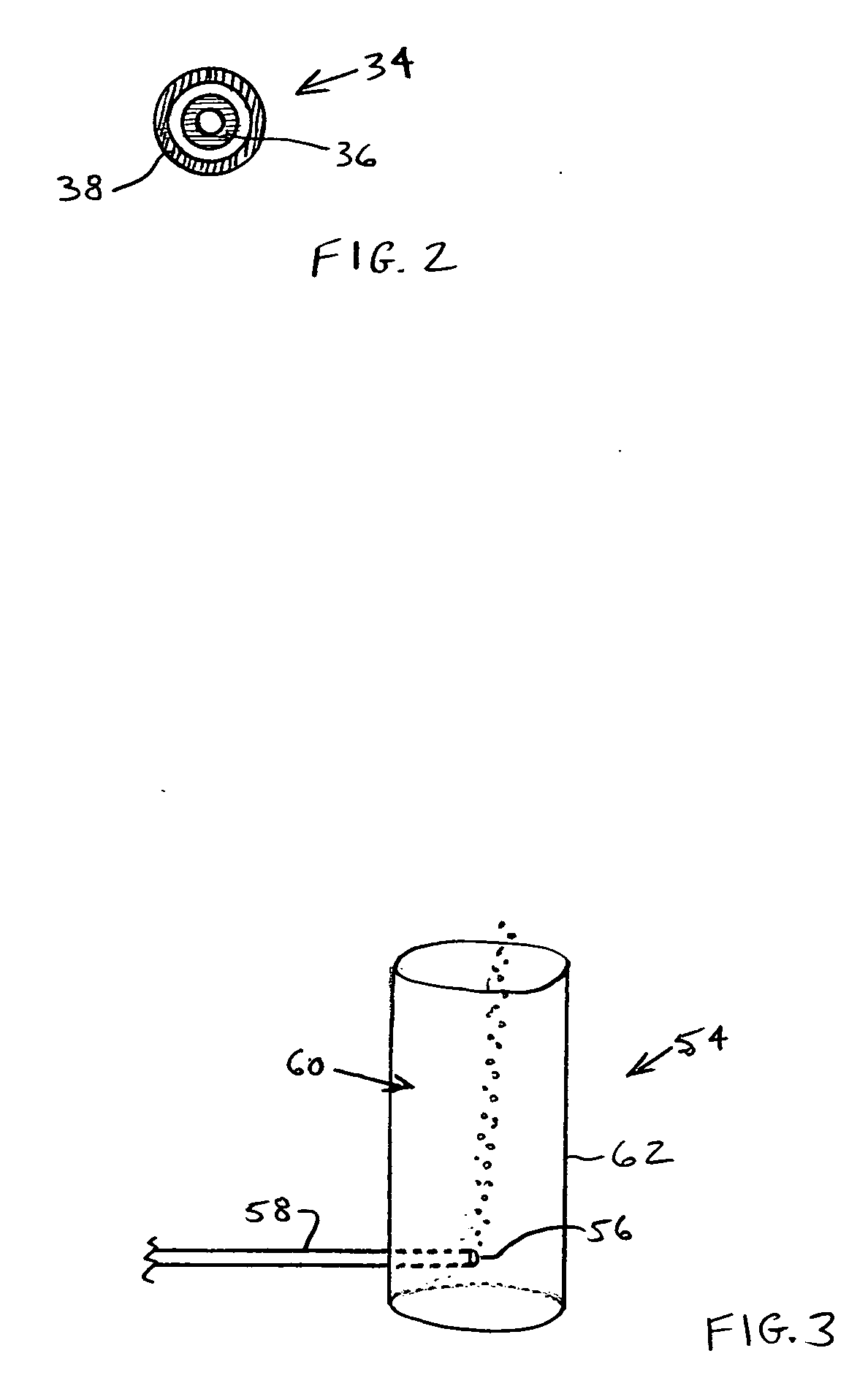
[0017] The present invention utilizes non-electric pressure transducers to dynamically provide a directly-measurable indication of the amount of fuel remaining in an aircraft fuel tank. In its most basic form, Teflon tubing is used to form fluid-conveying conduits that replace the prior art wired sensors. Thus, in one currently-preferred embodiment, at for example each tank bottom location of a prior art capacitive sensor, a distal open end of a length of Teflon tube is located closely proximate the tank bottom. The tubing is connected (exterior to the fuel tank) to a generator or supply of nitrogen, as for example an OBOG (On-Board Oxygen Generator) which has a semi-permeable membrane that, when pressure is applied to one side of the membrane, generates oxygen (which can be returned to the aircraft cabin) and nitrogen (for use in the inventive system). A relatively small, preferably constant volume flow of the OBOG-generated nitrogen is fed through each Teflon tube to bubble out th...


PUM


Abstract

Dynamic monitoring of the amount of fuel remaining in an aircraft fuel tank is effected by delivering a constant volume flow of an inert gas into the fuel through the respective open distal ends of a sensor conduit tube and a reference conduit tube, each of which extends from a proximal end exterior of the tank to its respective distal open end located within the fuel tank. The sensor conduit tube distal end is fixed closely proximate the bottom of the tank, and the reference conduit tube distal end is fixed proximate but at a vertical spacing h from the sensor conduit tube distal end. The pressure at which the gas is delivered into the fuel at the constant volumetric rate through each of the sensor and reference conduit tubes is monitored. The pressure difference between the monitored pressure in the sensor conduit tube and the pressure in the free space in the fuel tank above the surface of the remaining fuel is directly proportional to the weight of the fuel lying above the sensor conduit tube distal end. The density of the fuel is proportional to the monitored pressure difference between the sensor and reference conduit tubes, divided by the vertical spacing h. The calculated weight of the fuel, divided by the calculated density of the fuel, is proportional to the volume of the fuel remaining in the tank.

Description

RELATED APPLICATIONS [0001] This application claims priority from U.S. Provisional Patent Application Ser. No. 60 / 679,752 which was filed on May 11, 2005.FIELD OF INVENTION [0002] The present invention is broadly directed to the dynamic monitoring and measurement of the amount of fuel carried in a fuel tank of an aircraft and, more particularly, to systems and methods for dynamically determining the current weight, density and volume of fuel present in an aircraft fuel tank. BACKGROUND OF THE INVENTION [0003] Current aircraft fuel monitoring and indicating systems measure the fuel height and, separately, its density to calculate the weight of the fuel and, therefore, the remaining fuel capacity present in a fuel tank. In some such systems, for example, seven wired sensors, e.g. capacitive sensors, are variously placed about the bottom surface of the fuel tank—i.e. so that they are covered by the fuel in the tank. A predetermined profile is used to account for irregularities in the t...

Claims


Application Information

Patent Timeline
IPC IPC(8): G01F23/00G01N11/00
CPCB64D37/00B64D37/32G01N9/28G01F23/168G01F23/165G01F23/00G01N11/00
Inventor HEDRICK, GEOFFREY S.M.
Owner INNOVATIVE SOLUTIONS & SUPPORT
Why Eureka
Try Eureka