
Backpack sprayer

Inactive Publication Date: 2006-11-23
WIRZ PEDRO
View PDF11 Cites 45 Cited by
  • Summary
  • Abstract
  • Description
  • Claims
  • Application Information

AI Technical Summary

Benefits of technology

[0018] This invention provides such an improved device with an elegant solution to the problem that not only effectively and appropriately limits the movement of the piston within the cylinder, but also provides other benefits as well, such a protecting the piston and piston cylinder from physical damage, limiting their exposure to dust and other unwanted elements, and providing some protection to the operator and others in close proximity to the piston linkage from injury.
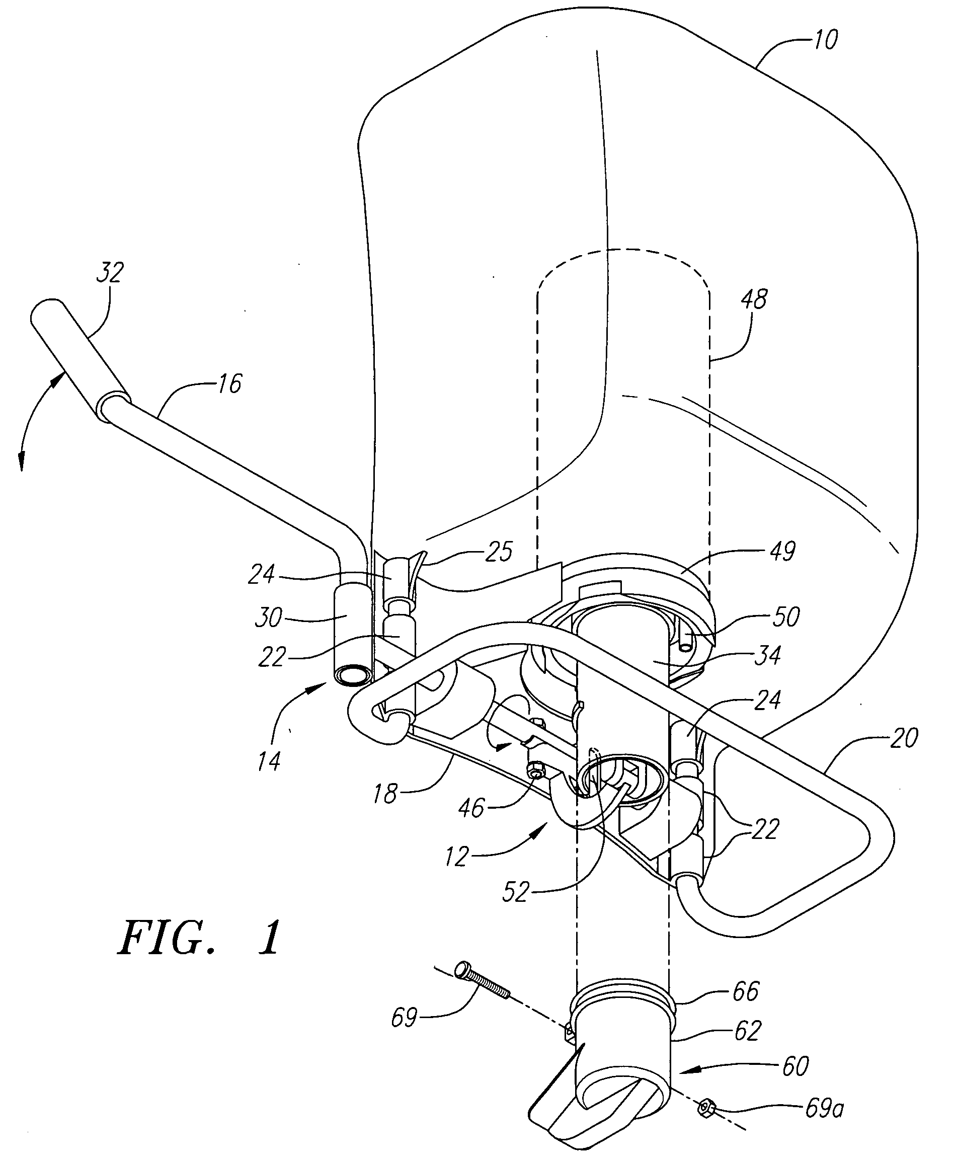
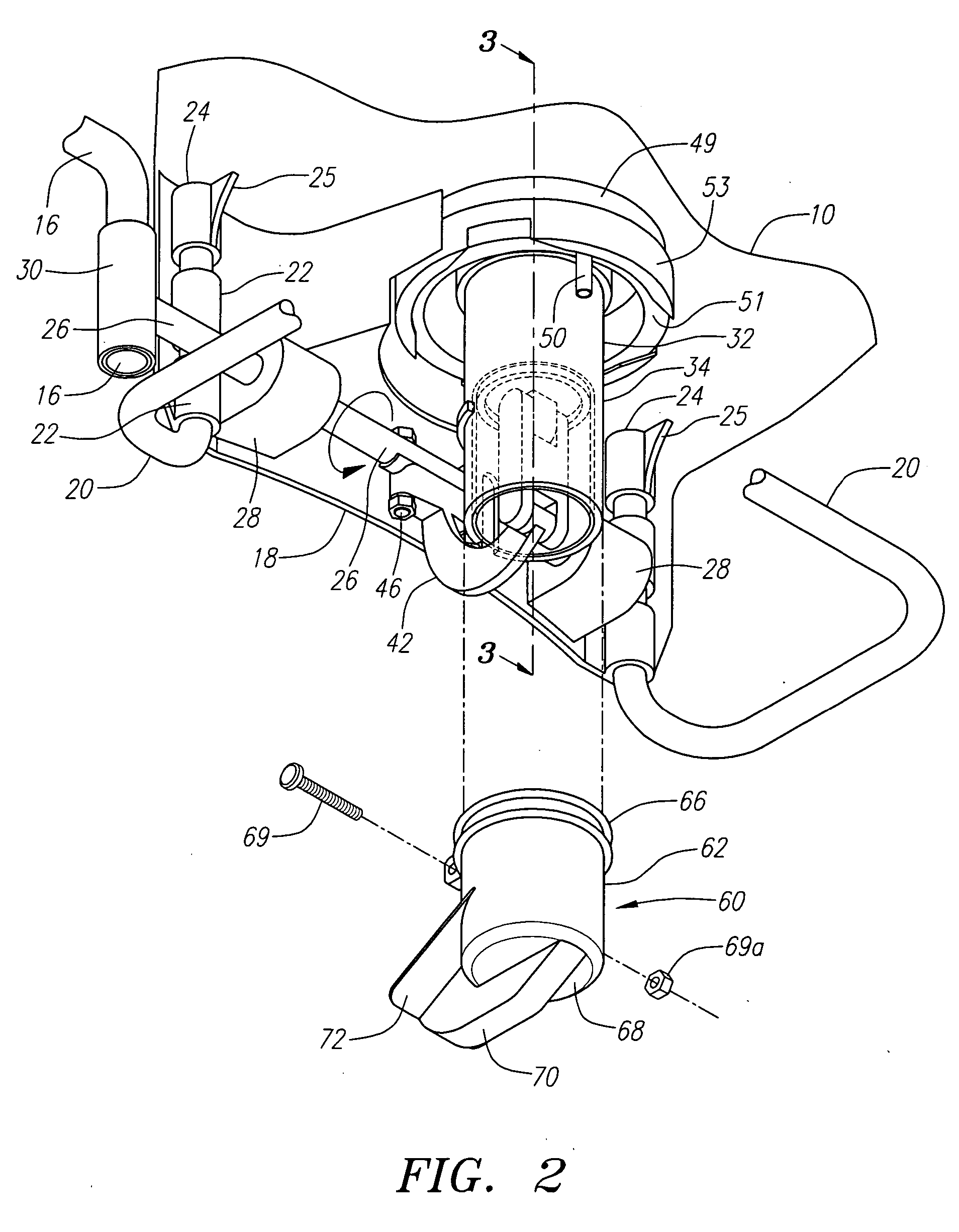
[0021] Therefore, in the preferred embodiment of this invention, the combination of the pegs on the bottom of the cap on the one hand, and the tabs and open area of the cap in conjunction with the exterior projection (or projections) on the cylinder on the other hand, act together to provide the restraining function that can withstand the forces generated by even the biggest, strongest and most aggressive operators on the down stroke of the piston, whether in a single event or repetitively over a long period of time.

Problems solved by technology

But there are innumerable instances in which the size or location of the job does not permit the use of such large equipment.
Such backpack sprayers are not new.
First, because the sprayer is worn by the operator in all types of weather, any leakage will be uncomfortable at least (no one likes to have liquid spilled down the back of their pants, particularly so in cold weather), and could be dangerous at most if the liquid being sprayed is a chemical that may present health risks to the operator if he or she is unduly exposed to the chemical.
Therefore, the sprayer must not only be capable of leak-free operation when it leaves the factory, it must remain leak-free during its lifetime of use, and these devices are expected to have a lengthy lifetime.
Also, the “use” to which these sprayers are most often put can create challenges for the designer to meet the design of goal of long-term durability and reliability while maintaining acceptable cost, ease of manufacture and resultant weight.
The sprayers may therefore be mishandled from time t0 time, not only during use but also after use when being stored or transported.
In use, the power that some operators can generate manually on the end of the handle bar is enormous, putting tremendous stress on the linkage and piston assemblies.
Before long, the operator has to apply tremendous force to the end of the handle bar.
Because of the leverage that is obtainable given the length of the handle and fact that the handle bar is attached to the linkage at one end, and the operator applies force at the other end, the resultant force that can be generated on the piston assembly can be huge.
Therefore, the use of large amounts of steel or other heavy gauge material is ultimately counterproductive.
But, while plastic does provide for reasonable strength and performance at low cost with light weight, it simply cannot generally withstand the forces generated by many operators.
Because the piston cylinders in the sprayers can be quite large, it is undesirable to use steel or other heavy gauge material for the cylinder as that would add materially to cost and weight.
But, the piston and cylinder, and the adjacent linkage, are where the greatest forces must be accommodated, and is also the area where damage and leakage can most readily occur.
Otherwise, the piston is pulled out of alignment with the cylinder resulting in one or more undesirable things: 1) the liquid in the tank may leak out of the device onto the operator; 2) the rubber seal on the head of the piston may become unattached; and 3) in extreme cases, the piston and / or the piston cylinder cracks, rendering the device useless until repaired.
That, however, proved unworkable because even a large metal pin could be bent if sufficient force were applied to the handle bar by the operator.
This too proved unworkable as the force that could be generated by some operators over time would cause sufficient deformation of the wedge that it ceased to function properly.
While these prior art devices are useful to a degree, they still suffer from certain drawbacks in that they did not provide sufficient durability and reliability.

Method used


Image

  • Backpack sprayer
  • Backpack sprayer
  • Backpack sprayer

Examples


Embodiment Construction

[0030] Throughout this Specification and the attached Claims, reference to direction such as “top,”“above” or “upwardly” etc. shall refer to the upward direction for the components as oriented and shown in the Figures; whereas references to “bottom,”“down” and “below” etc. shall refer to the downward direction for the components as oriented and shown in the Figures, which is how the sprayer would be oriented when attached to the back of the operator ready for use. References to “front” or “side” or “back” are used relative to the operator upon whom the sprayer is attached. For example, the “front” refers to the side or direction facing in the same direction as the operator would be facing.

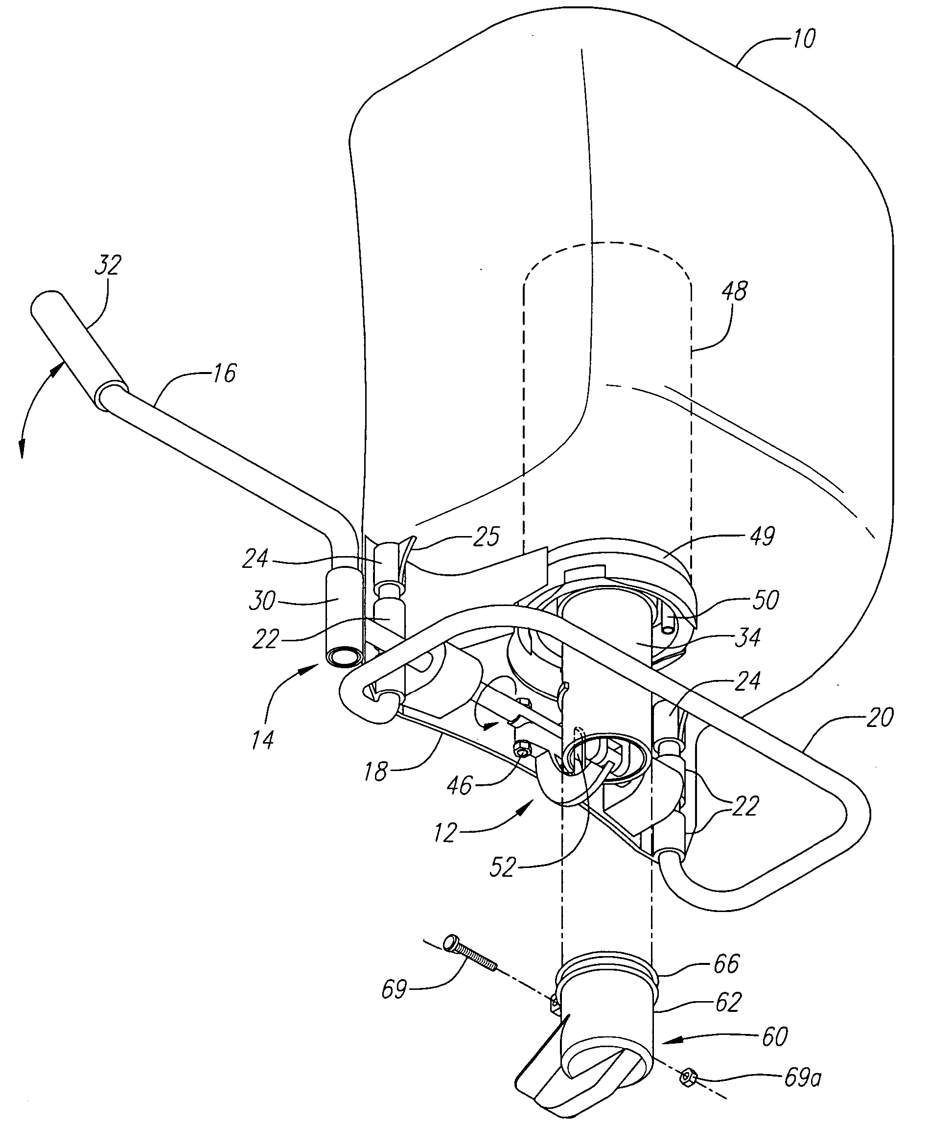
[0031] Looking at FIG. 1, it is seen that the preferred embodiment of this invention has the usual primary components for a high-end backpack sprayer—the tank 10, the piston assembly 12, the linkage assembly 14, and the handle bar 16. (The straps that are used to secure the sprayer to the operator...


PUM


Abstract

A backpack sprayer having a tank, an interior pressure chamber, and a piston assembly that is used to draw fluid into the pressure chamber and also to pressurize the chamber so as to expel the fluid under pressure, which piston assembly is connected by a linkage assembly to a handle bar that is manually operated by the operator of the sprayer to cause movement of the piston within a piston cylinder, the improvement including a piston cylinder cap that attached to the end of the piston cylinder and restrains downward movement of the piston arm.

Description

BACKGROUND OF THE INVENTION [0001] This invention relates generally to a mechanical pumping device that utilizes a piston mechanism to create pressure within a confined space. In particular, this invention pertains to such a device that is particularly well adapted for use in a manually-operated backpack sprayer. [0002] Just about every home, garden, landscape, farm, ranch and business requires, at one time or another, the application of a liquid-based substance in a localized way. For example, in and around every home isolated plants may need to be watered that cannot be easily watered with a garden hose, or an herbicide, pesticide, fungicide, fertilizer or other chemical agent may need to be applied. Such applications are an almost daily requirement on most farms and ranches, and around many homes and business. [0003] For large applications, motorized spraying units on wheeled vehicles are commonly used. But there are innumerable instances in which the size or location of the job ...

Claims


Application Information

Patent Timeline
IPC IPC(8): A01G25/09B05B9/00B05B3/18B05B9/03
CPCB05B9/0877A01M7/0046
Inventor WIRZ, PEDRO
Owner WIRZ PEDRO
Learn More