Flow control system with variable staged adjustable triggering device

Active Publication Date: 2016-10-11
SCHLUMBERGER TECH CORP
View PDF18 Cites 1 Cited by
  • Summary
  • Abstract
  • Description
  • Claims
  • Application Information

AI Technical Summary

Benefits of technology

[0002]In general, the present disclosure provides a system and method for controlling flow, e.g. controlling flow along a wellbore. A flow control assembly, e.g. an in-line barrier valve, is placed along a flow passage. A bypass is routed past the flow control assembly. Flow along the bypass is controlled via a flow bypass mechanism which may be operated interventionless by, for example, pressure, e.g. a pressure differential, pressure pulse, absolute pressure, or other suitable interventionless technique. The in

Problems solved by technology

Accidental or inadvertent closing or opening of in-line barrier valves can result in a variety of well system failures.
In some a

Method used


Image

  • Flow control system with variable staged adjustable triggering device
  • Flow control system with variable staged adjustable triggering device
  • Flow control system with variable staged adjustable triggering device

Examples


Example

[0011]In the following description, numerous details are set forth to provide an understanding of the present invention. However, it will be understood by those skilled in the art that the present system and / or methodology may be practiced without these details and that numerous variations or modifications from the described embodiments may be possible.

[0012]In the specification and appended claims: the terms “couple”, “coupling”, “coupled”, “coupled together”, and “coupled with” are used to mean “directly coupled together” or “coupled together via one or more elements”. As used herein, the terms “up” and “down”, “upper” and “lower”, “upwards” and downwards”, “upstream” and “downstream”; “above” and “below”; and other like terms indicating relative positions above or below a given point or element are used in this description to more clearly describe some embodiments. However, when applied to equipment and methods for use in environments that are deviated or horizontal, such terms m...


PUM


Abstract

Techniques and equipment to facilitate controlling flow of a fluid along a flow passage. A flow control assembly is placed along a flow passage, and a bypass is routed past the flow control assembly. Flow along the bypass is controlled by a flow bypass mechanism which may be operated via pressure increase within the flow control assembly. A shear device restricts the opening of the bypass, and a dampening device acts to limit the shear device to exposure of forces from the pressure increase.

Description

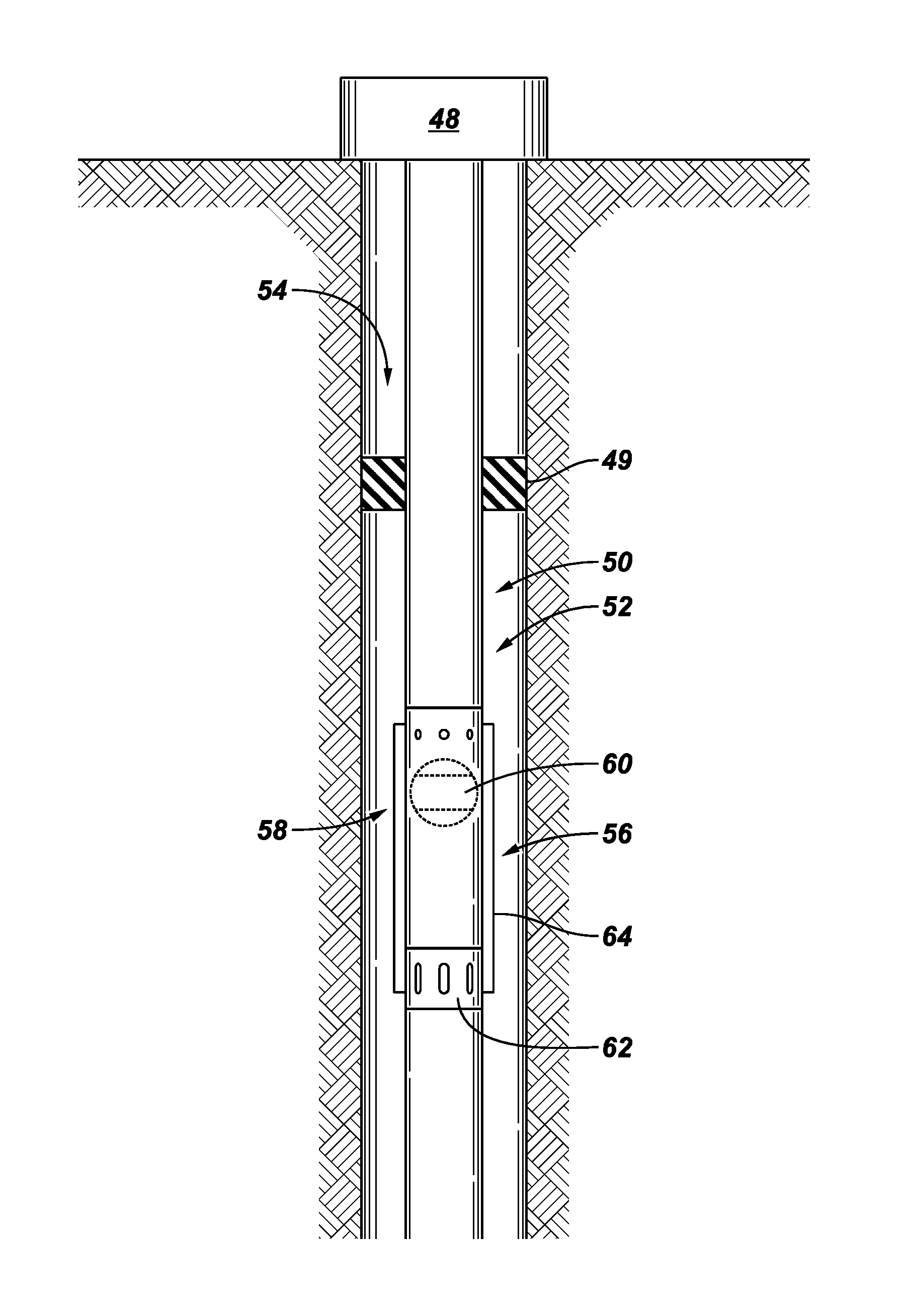
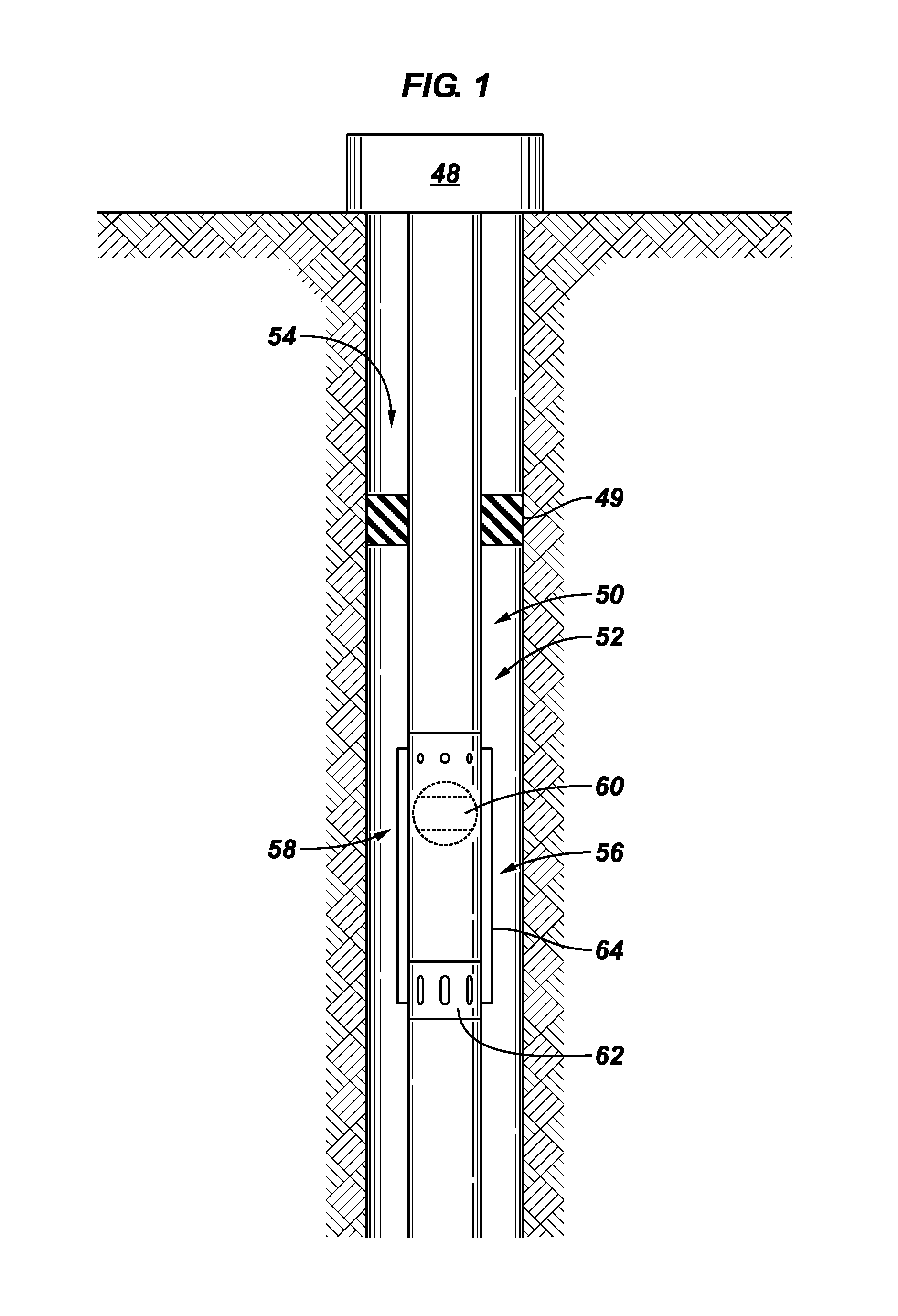
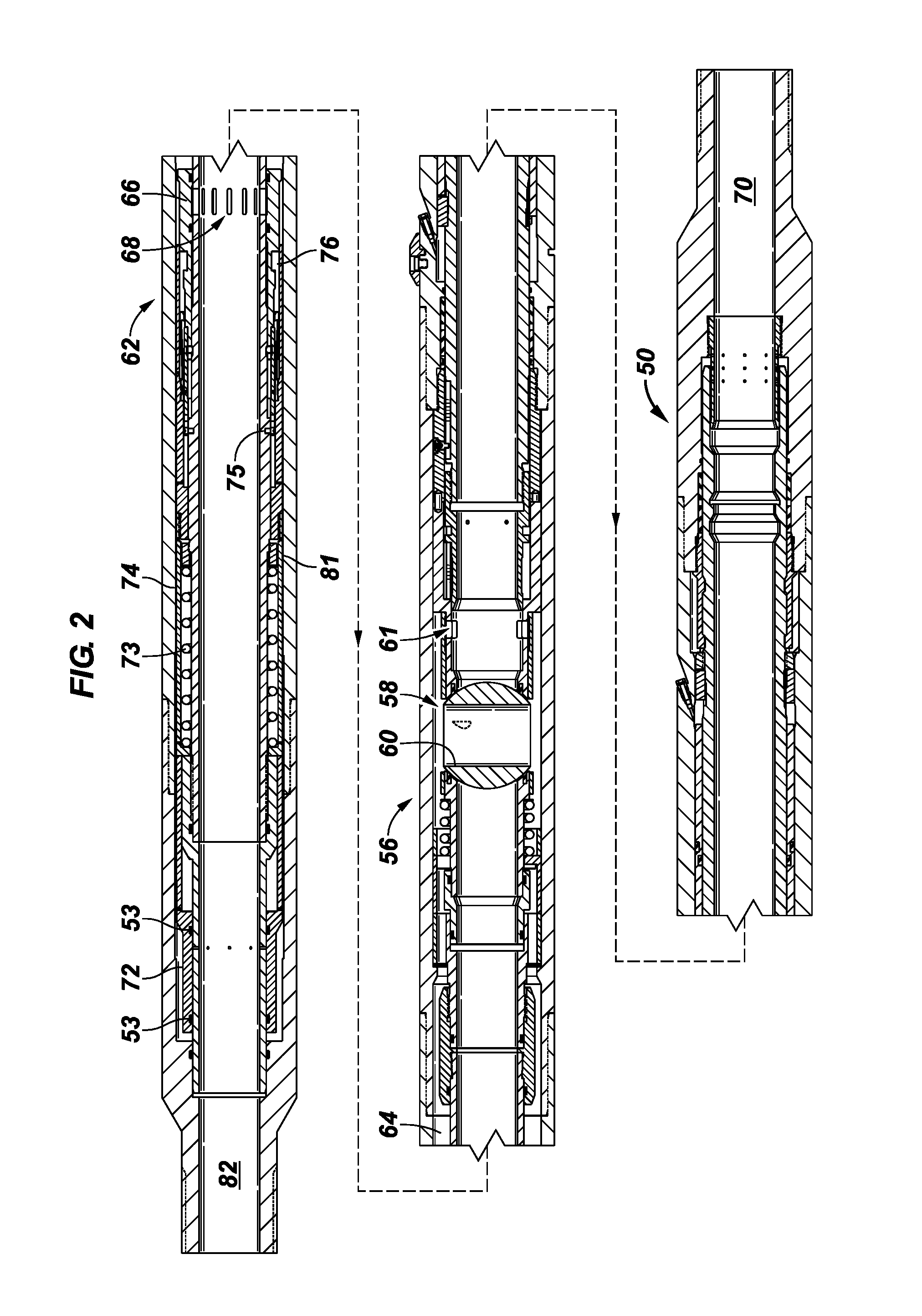
BACKGROUND[0001]Hydrocarbon fluids such as oil and natural gas are obtained from a subterranean geologic formation, referred to as a reservoir, by drilling a well that penetrates the hydrocarbon-bearing formation. Once a wellbore is drilled, various forms of well completion components may be installed in order to control and enhance the efficiency of producing the various fluids from the reservoir. In a variety of downhole applications, flow control devices, e.g. in-line barrier valves, are used to control flow along the well system. Accidental or inadvertent closing or opening of in-line barrier valves can result in a variety of well system failures. In some applications, adverse formation issues may occur in a manner that initiates pumping of heavier fluid for killing of the reservoir. In such an event, the in-line barrier valve is opened to allow pumping of kill weight fluid.SUMMARY[0002]In general, the present disclosure provides a system and method for controlling flow, e.g. co...

Claims


Application Information

Patent Timeline
IPC IPC(8): E21B34/00E21B34/08E21B34/14E21B34/10E21B34/06
CPCE21B34/06E21B34/063E21B34/08E21B34/101E21B34/102E21B34/103E21B34/14E21B2034/002E21B2200/04
Inventor ANYAN, STEVEN L.MARTINEZ, RICARDOLEONARDI, TAUNA
Owner SCHLUMBERGER TECH CORP
Why Eureka
Try Eureka