
Motor-operated valve

a motor-operated valve and valve body technology, which is applied in the direction of valve operating means/release devices, machines/engines, mechanical apparatus, etc., can solve the problems of poor control of the prior art, low control of excessive change in the flow rate of refrigerant, so as to improve the resolution of the valve opening with respect to the rotation angle of the rotor, and achieve more accurate control

Inactive Publication Date: 2006-11-23
FUJIKOKI CORP
View PDF6 Cites 13 Cited by
  • Summary
  • Abstract
  • Description
  • Claims
  • Application Information

AI Technical Summary

Benefits of technology

The present invention provides a motor-operated valve with a novel construction that can control the flow rate of refrigerant finely without causing hindrance to rotation regulation even when using high-pressure refrigerant. The valve includes a rotor and stator, and the rotational motion of the rotor is converted into linear motion by a screw mechanism. The screw mechanism is formed by a differential screw with two screw portions having the same direction but different pitch. The valve also includes a screw feed member, stem member, valve stem, and external thread member. The differential screw mechanism improves the resolution of valve opening with respect to the rotation angle of the rotor, resulting in more accurate control.

Problems solved by technology

However, in particular, in a motor-operated valve (used as an expansion valve) used for a refrigerator or the like, the control in the prior art is rough although the controlled refrigerant flow rate is very low.
In the case where the high-pressure refrigerant is used, if the valve element is lifted at intervals of 0.6 [mm], there arises a problem in that a change in flow rate of the refrigerant becomes too great.
However, the decrease in effective opening area has a limitation, and only such a measure cannot solve the above-described problem completely.
However, if the pitch of the screw mechanism is decreased, a highly accurate fabrication is required, and thus the fabrication cost increases.
In addition, there arises a problem in that the lift amount per one rotor rotation is small, so that the contact and separation of a movable stopper with and from the fixed stopper, these stoppers being used to regulate rotation, are not accomplished properly.

Method used


Image

  • Motor-operated valve
  • Motor-operated valve
  • Motor-operated valve

Examples


Embodiment Construction

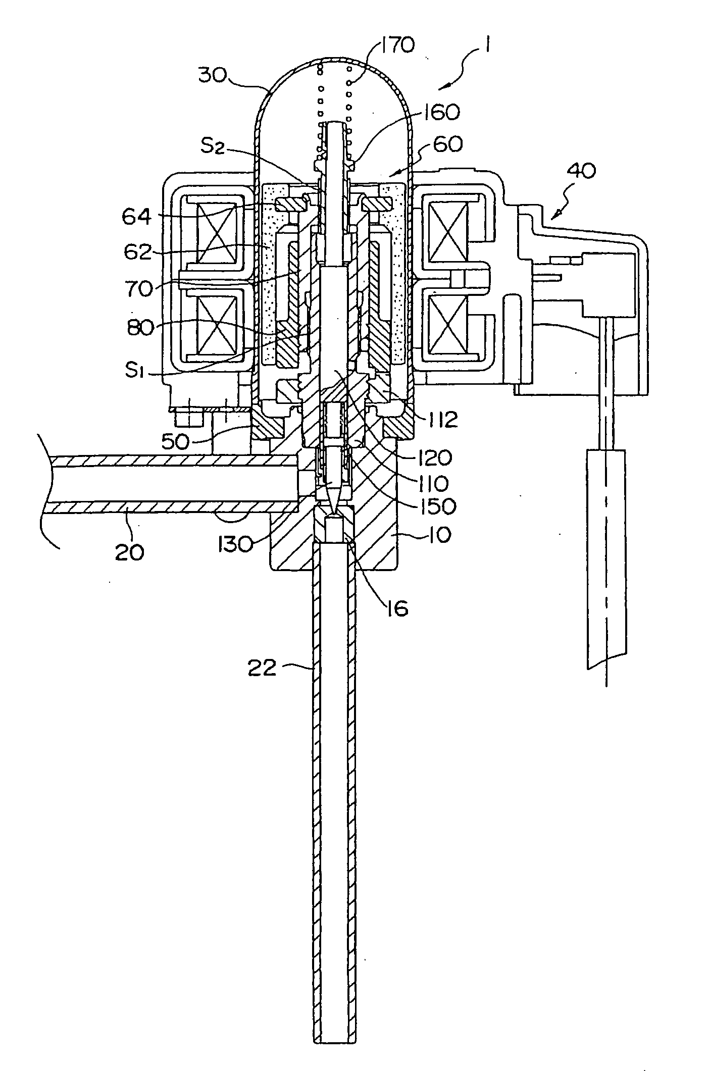
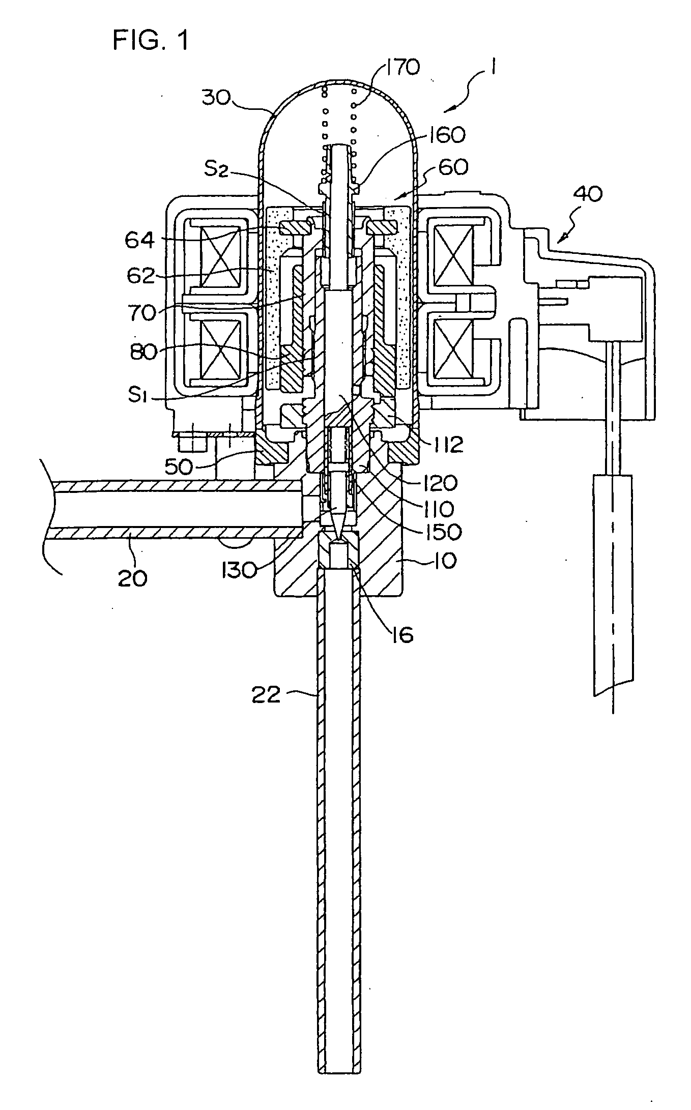
[0024]FIG. 1 shows the entire construction of a motor-operated valve in accordance with the present invention.

[0025] A motor-operated valve the whole of which is denoted by reference numeral 1 has a valve body 10, and a valve seat member 16 is inserted in the valve body 10. The valve body 10 is connected with pipes 20 and 22.

[0026] In the upper part of the valve body 10, a can 30, which is a cylindrical pressure vessel, is fixed via a supporting member 50. On the outside of the can 30, a stator unit 40 of a stepping motor, which is used as one example of drive motor, is mounted.

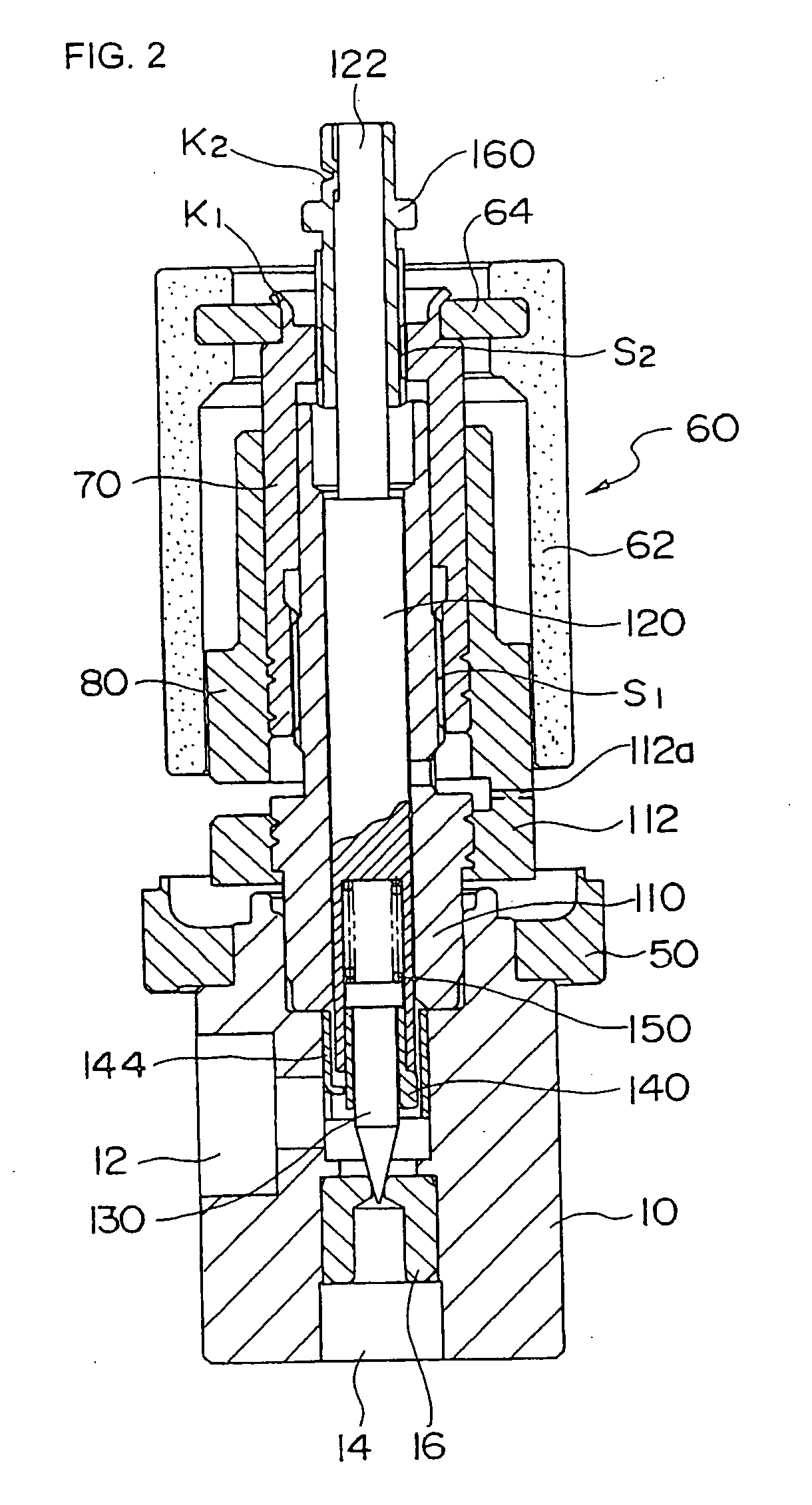
[0027] In the can 30, a rotor unit 60 is rotatably disposed. The rotor unit 60 includes a rotor 62 consisting of a plastic magnet formed by mixing a magnetic material in a resin, and a screw feed member 70 connected to the rotor 62 via a ring member 64.

[0028] The screw feed member 70 has a first screw portion S1 and a second screw portion S2, which are formed in the same turning direction, and the pitch o...


PUM


Abstract

A motor-operated valve has a rotor unit in a can, and is rotationally driven by a stator unit. The rotation of the rotor unit is transmitted to a screw feed member. A stem member fixed to a valve body is engaged threadedly with the screw feed member by a first screw portion. At the same time, the screw feed member is engaged threadedly with an external thread portion fixed to a valve stem by the second screw portion. The first screw portion and the second screw portion constitute a differential screw mechanism, and feeds the valve stem according to a difference in pitch.

Description

[0001] The present application is based on and claims priority of Japanese patent application No. 2005-146188 filed on May 19, 2005, the entire contents of which are hereby incorporated by reference. BACKGROUND OF THE INVENTION [0002] 1. Field of the Invention [0003] The present invention relates to a motor-operated valve used by being assembled into an air conditioner, a refrigerator, or the like and, more particularly, to a motor-operated valve capable of controlling the flow rate of a refrigerant accurately to a minute amount even in the case where a high-pressure refrigerant is used. [0004] 2. Description of the Related Art [0005] For example, Patent Reference 1 describes a conventional general motor-operated valve. This motor-operated valve has a mechanism in which a rotor disposed on the inside of a can is rotationally driven by a stator provided on the outside of the can, and the rotational motion of rotor is converted into linear motion by a screw mechanism, by which the val...

Claims


Application Information

Patent Timeline
Patent Type & Authority Applications(United States)
IPC IPC(8): F16K31/02
CPCF02M25/0773F16K1/04Y02T10/121F16K31/506F16K31/04F02M26/54F16K31/06F16K31/00
Inventor INOUE, YASUSHIHIGUCHI, KOUJIUMEZAWA, HITOSHI
Owner FUJIKOKI CORP
Learn More