Structure of angular pneumatic gripper

a technology of angular pneumatic chuck and structure, which is applied in the direction of clamps, manipulators, load-engaging elements, etc., can solve the problems of inability to apply forming techniques to the realisation of the angular pneumatic chuck in question, and the similar construction process of the said chuck is extremely laborious and costly, so as to achieve the effect of reducing the time and cost of construction and assembly

Active Publication Date: 2006-11-23
GIMATIC SRL
View PDF8 Cites 6 Cited by
  • Summary
  • Abstract
  • Description
  • Claims
  • Application Information

AI Technical Summary

Benefits of technology

[0006] An objects of this invention is to adopt advantageously some of the forming techniques mentioned above in the realisation of

Problems solved by technology

A similar construction process of said chucks is however extremely laborious and costly due to the machining operations and the work times required and often because of the minimum machining

Method used


Image

  • Structure of angular pneumatic gripper
  • Structure of angular pneumatic gripper
  • Structure of angular pneumatic gripper

Examples


Embodiment Construction

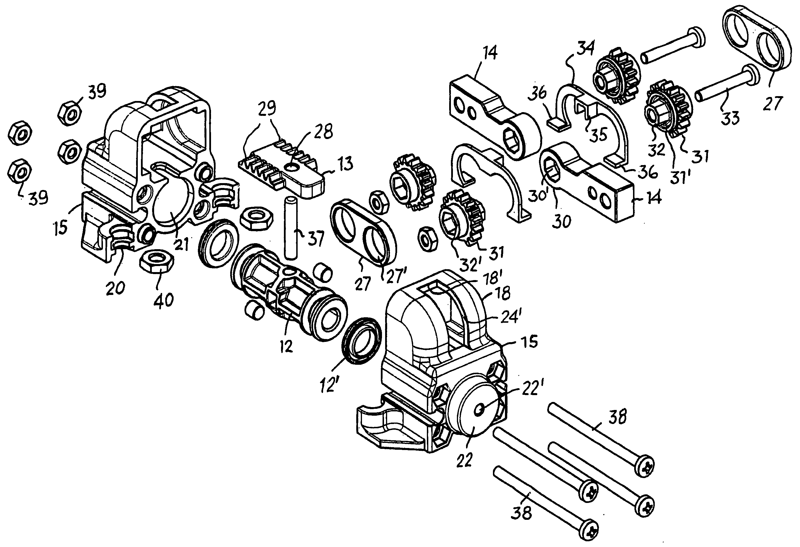
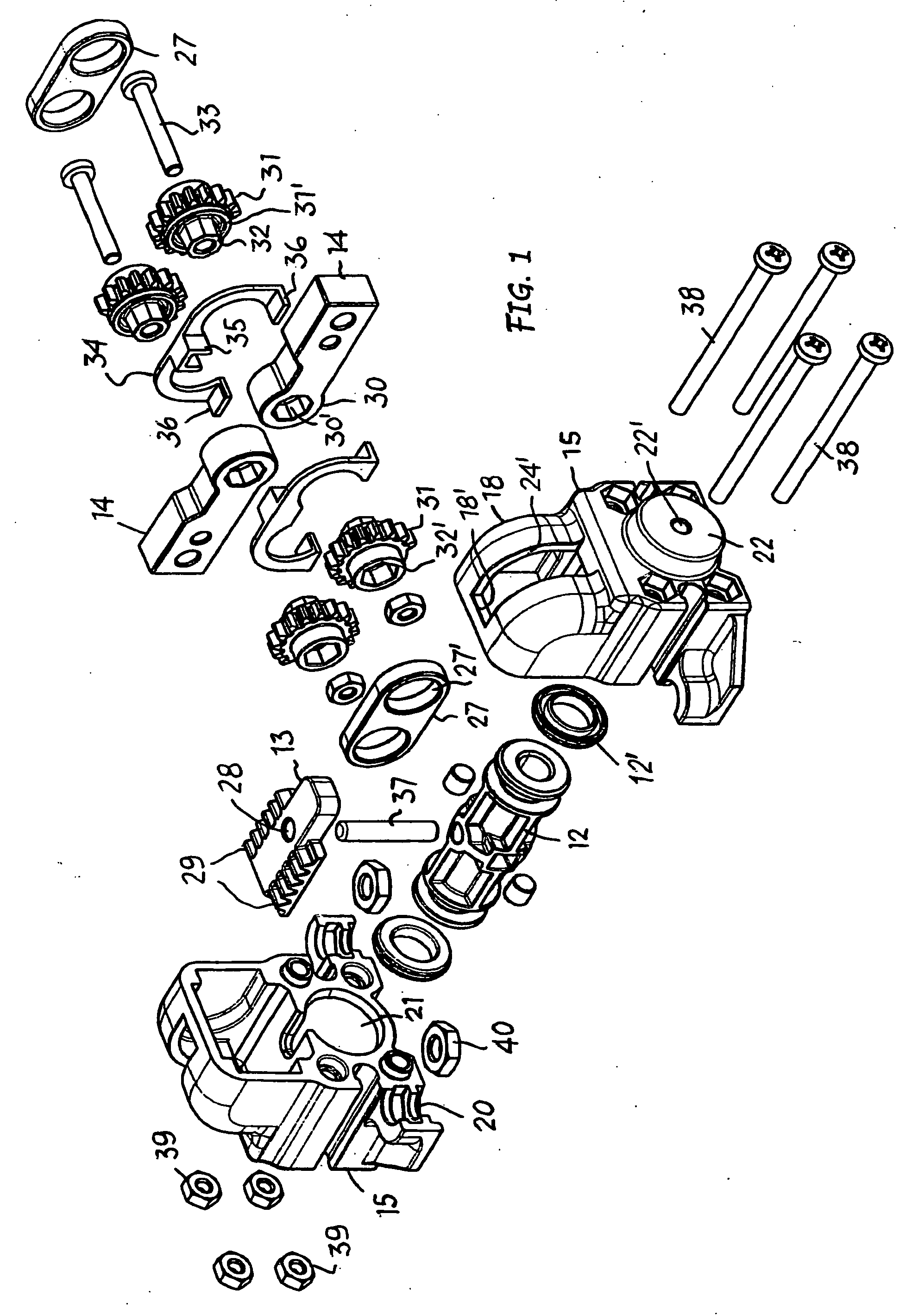
[0018] The angular pneumatic gripper shown comprises a body 11, a piston 12 moving in said body, a drive 13 associated with the piston 12, two grips 14, turning in opposite directions, each on its own pin or axis 14′, moved by the piston 12 through of the drive 13, and two gripper jaws, not shown, attached to the ears.

[0019] The body 11 is made up of two symmetric elements or shells 15 which are identical and therefore made using the same mould, advantageously using die-casting, sintering or forging forming processes using any appropriate raw material.

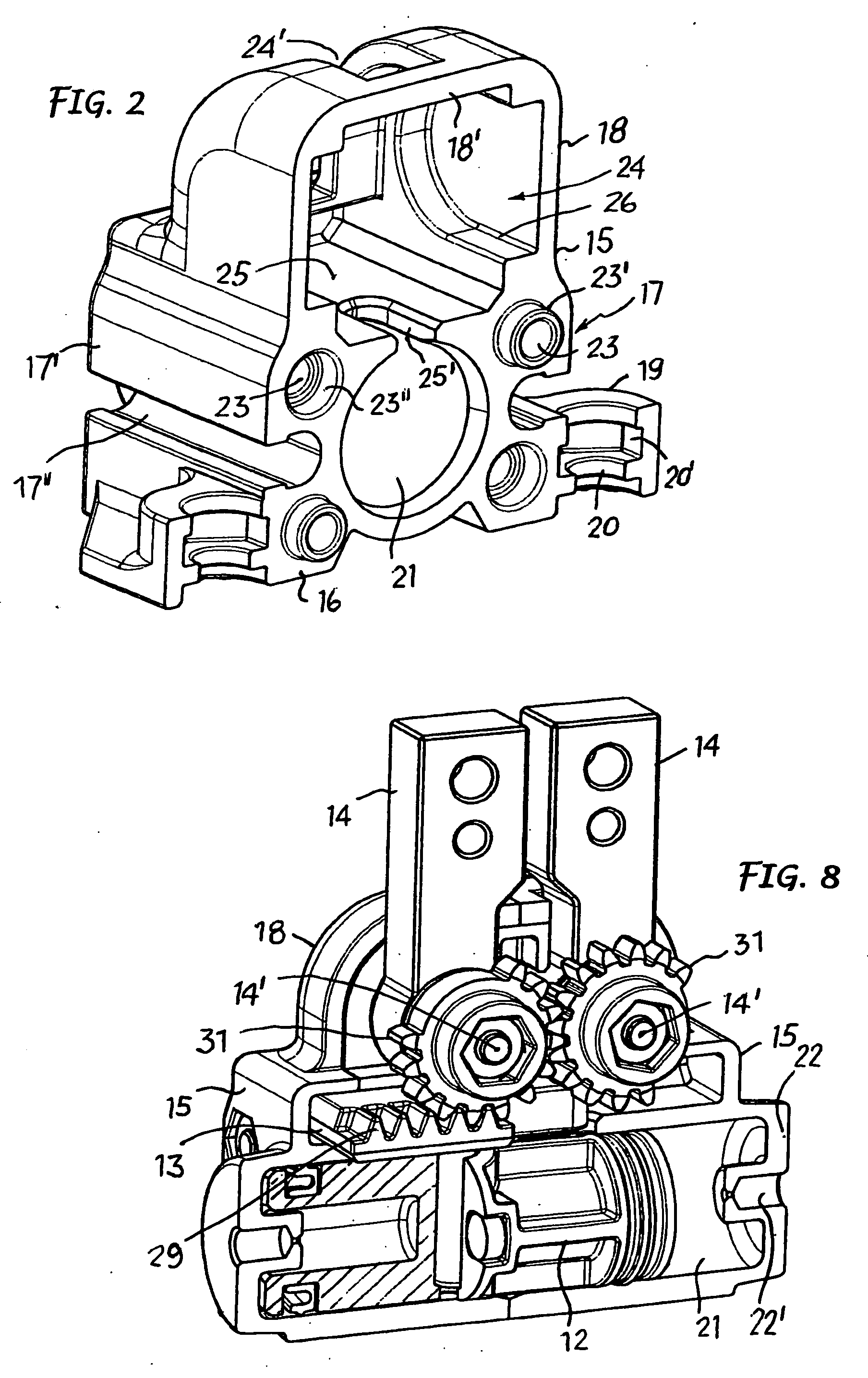
[0020] The two shells 15 are positioned one facing the other. They are matched and then attached to each other as will be described below. Each of them—FIG. 2—has a support base 16 from which an intermediate section 17 rises overlooked by two shoulders 18 connected by a top crosspiece 18′.

[0021] Two ears 19 protrude from opposite sides if the support base 16, each one having a semi-hole 20, perpendicular to the base, opening towards...


PUM


Abstract

The invention concerns an angular pneumatic gripper structure having a body (11) formed of two symmetric and identical elements or shells (15) realised and finished individually using a forming process and then associated and attached face to face to form together a housing chamber of an alternating piston (12) and means for receiving and guiding an intermediate drive (13) transversely and some grips (14) so as to turn driven by the piston through the drive. The elements or shells forming the body are made using die-casting, sintering or forging processes with material suitable for these forming techniques.

Description

FIELD OF INVENTION [0001] This invention concerns in general pneumatic grippers for gripping items being machined and / or automatic handling, and refers in particular to improved components for making ready angular pneumatic grippers, that is to say with two jaw holding grips capable of angular movements in opposite closing and opening directions. STATE OF THE ART [0002] The pneumatic grippers taken into consideration can be different in shape, dimensions and capacity, but each one usually includes a body, a pneumatic piston moving backwards and forwards in a chamber or sleeve in said body, two grips supported and powered in the body, coupled to the piston through a drive, and two jaws fixed to the grip to block an release the item to be handled. The grip are mobile angularly in opposite directions between the opening and closing positions by means of the drive and in response to the alternative movements of the piston. Their rotation can be chosen or adjusted so that, starting from ...

Claims


Application Information

Patent Timeline
IPC IPC(8): B25J15/08B25B5/06B25J15/02
CPCB25B5/061B25J15/0213B25B5/064
Inventor MAFFEIS, GIUSEPPE
Owner GIMATIC SRL
Why Eureka
Try Eureka