Adjustable mirror

Inactive Publication Date: 2006-11-23
KONINKLIJKE PHILIPS ELECTRONICS NV
View PDF12 Cites 11 Cited by
  • Summary
  • Abstract
  • Description
  • Claims
  • Application Information

AI Technical Summary

Benefits of technology

[0010] It is an aim of particular embodiments of the present invention to provide an adjustable mirro

Problems solved by technology

Such deformable mirrors are susceptible to wear, as the mirror is continually stressed and de-stressed to obtain the desired shape.
Further, deforming the reflective surface in the desired manner is difficult to control, and consequently it is relatively expensive to provide a deformable

Method used


Image

  • Adjustable mirror
  • Adjustable mirror
  • Adjustable mirror

Examples


first embodiment

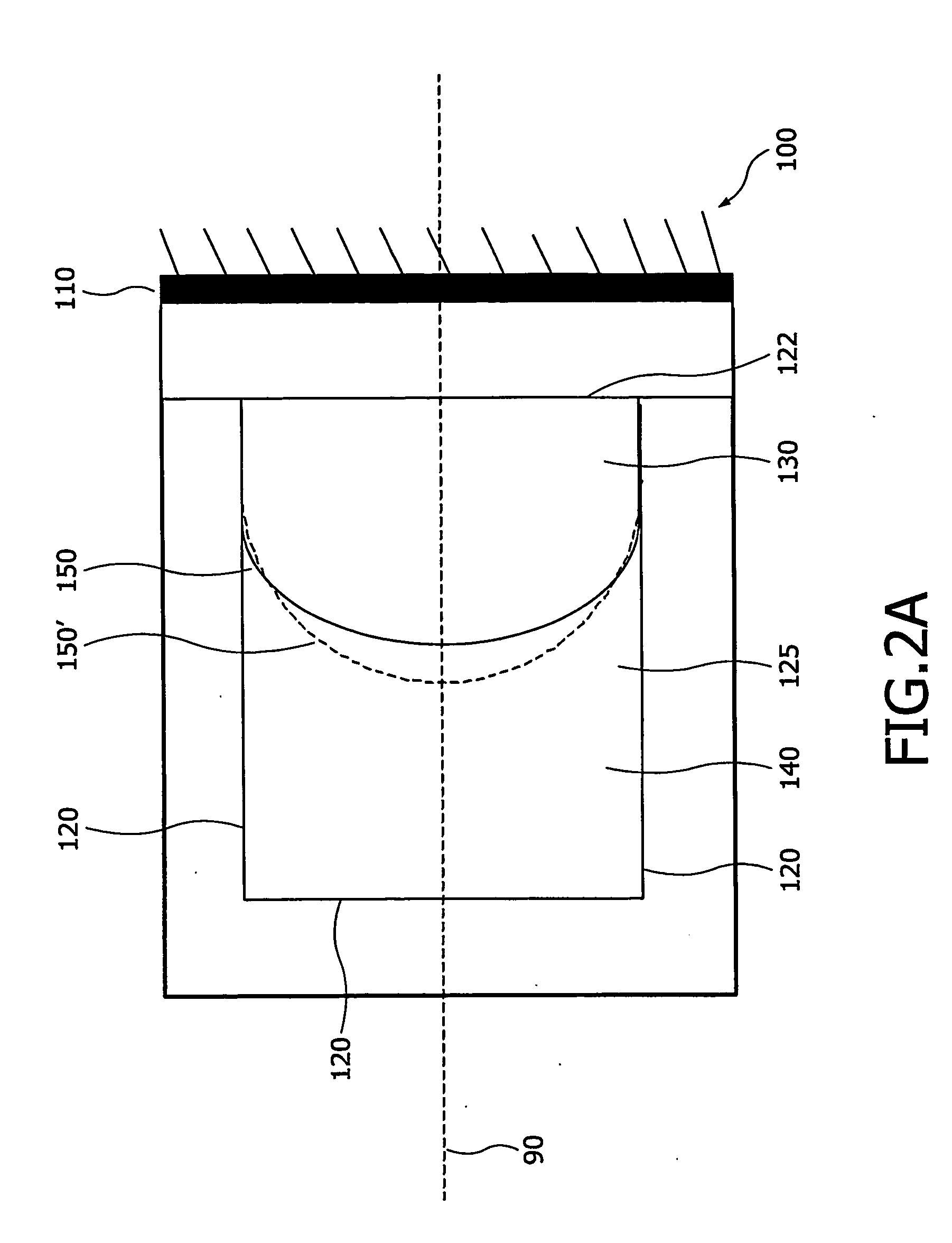
[0026]FIG. 2A shows an adjustable mirror 100 in accordance with the present invention. The mirror 100 can be regarded as being formed of two distinct elements: a reflective surface 110 and a variable lens formed of two fluids 130, 140 of different refractive indices.

[0027] A fluid is a substance that alters its shape in response to any force, that tends to flow or to conform to the outline of its chamber, and that includes gases, liquids and mixtures of solids and liquids capable of flow.

[0028] The two fluids are substantially immiscible i.e. the two fluids do not mix. A lens function is thus provided by the meniscus 150 formed along the contact area between he two fluids, as the fluids have different refractive indices. A lens function is the ability of the meniscus 150 to focus (converge or diverge) one or more wavelengths of light.

[0029] The meniscus 150 extends transverse the optical axis 90 of the mirror 100. The term transverse indicates that the meniscus crosses (i.e. it ex...

second embodiment

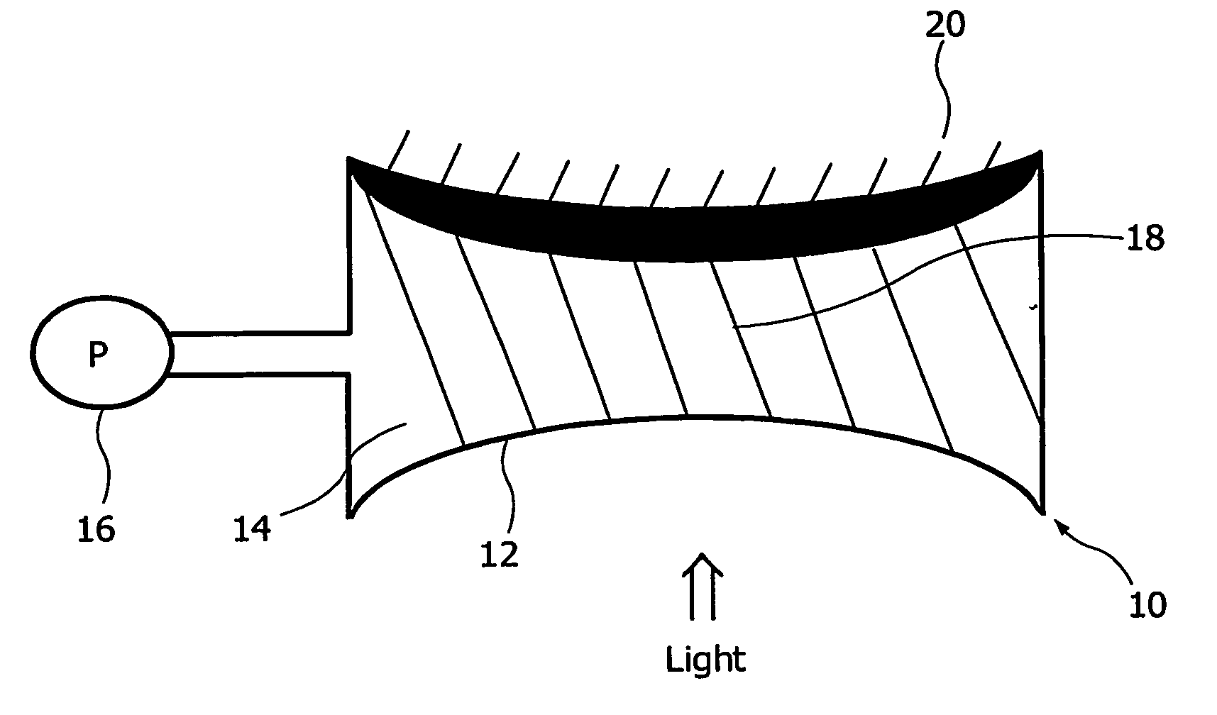
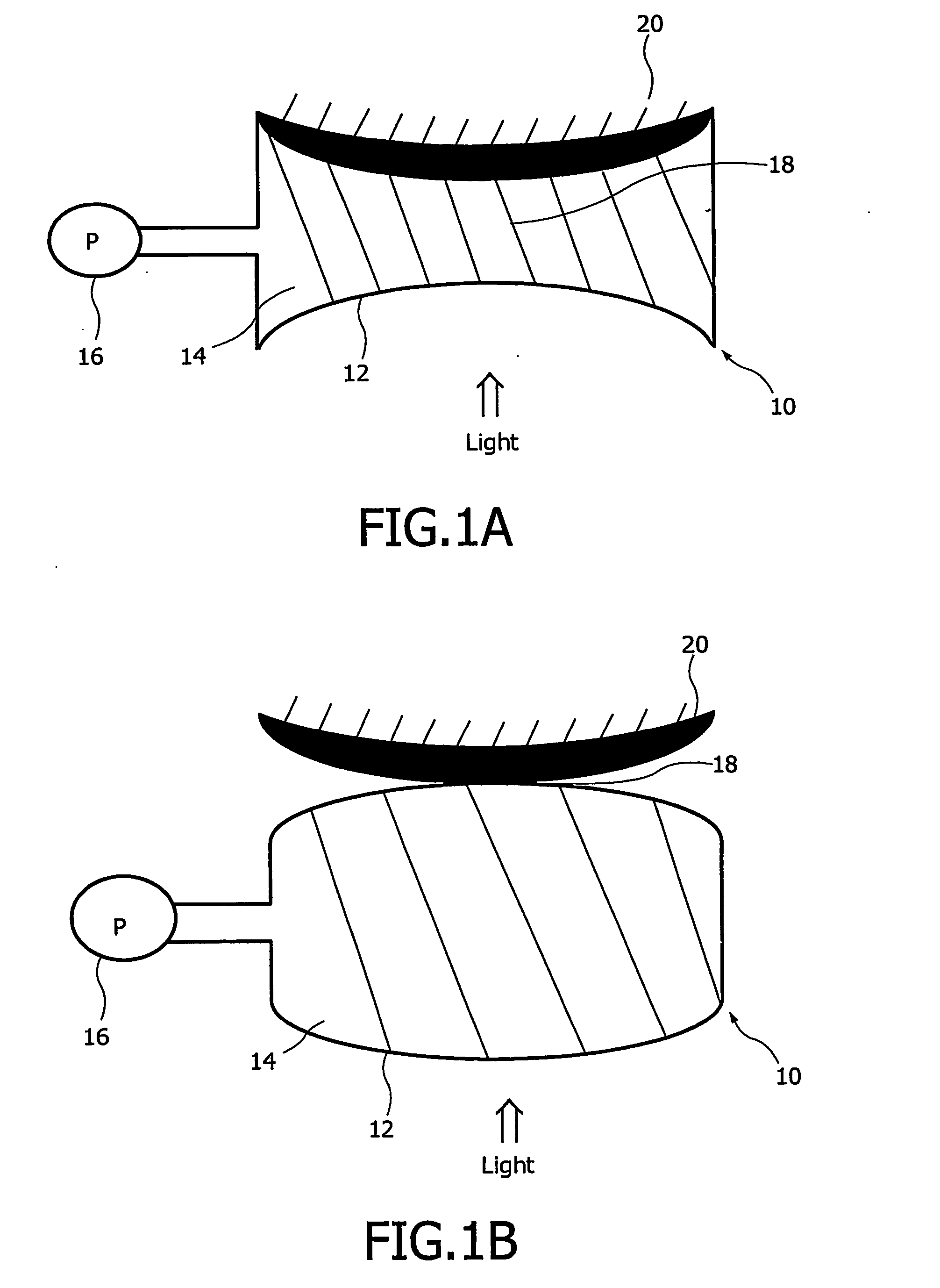
[0047]FIG. 4A illustrates a cross sectional schematic view of an adjustable mirror 300 in accordance with the present invention. The mirror 300 is generally similar to the mirror 100 illustrated in FIG. 2A, with identical reference numerals being utilised to indicate similar components. In this particular embodiment, the adjustable mirror 300 further comprises a pump 30 connected to the fluid filled chamber 125 and arranged to pump quantities of one or more of the fluids to and from the chamber 125. In this particular example, the pump 310 is arranged to simultaneously increase the volume of the fluid 130 and the decrease the volume of the fluid 140 (and vice versa), so as to maintain the same total volume of the two fluids 130, 140 within the chamber 125. The result will be that the meniscus 150 will be moved along the optical axis as fluids are added i.e. if extra fluid 130 is added, then the meniscus may move to position 150″. In this particular embodiment, the shape of the menis...


PUM


Abstract

An adjustable mirror comprises: a first fluid and a second fluid in contact over a meniscus extending transverse an optical axis. The fluids are substantially immiscible and have different indices of refraction. A reflective surface extends transverse the optical axis. A meniscus adjuster is arranged to controllably alter at least one of the shape and the position of the meniscus.

Description

FIELD OF THE INVENTION [0001] The present invention relates to adjustable mirrors, to optical devices including adjustable mirrors, and to methods of manufacturing such mirrors and such devices. BACKGROUND OF THE INVENTION [0002] A mirror is a device that is arranged to reflect light. The term light is understood to include both visible electromagnetic radiation, and other wavelengths of electromagnetic radiation. [0003] An adjustable mirror is a mirror in which the reflective properties of the mirror can be controllably adjusted. For instance, the shape (or apparent shape) of the reflecting surface may be altered, or the position (or apparent position) of the reflecting surface may be altered. [0004] One type of adjustable mirror is the deformable mirror, in which the reflective surface of the mirror can be controllably deformed so as to provide a desired shape. For instance, the reflective surface of a spherical mirror may be controllably deformed so as to alter the radius of curv...

Claims


Application Information

Patent Timeline
IPC IPC(8): G02B5/08G02B3/14G02B26/02G02B26/08H01S3/08H01S3/105
CPCG02B3/14G02B26/005H01S3/105H01S3/08059G02B26/0816G02B26/02H01S5/183
Inventor HENDRIKS, BERNARDUS HENDRIKUS WILHELMUSKUIPER, STEIN
Owner KONINKLIJKE PHILIPS ELECTRONICS NV
Why Eureka
Try Eureka