An artificial tooth, a jig for arranging the same, an arrangment method of the same and a denture

a technology of artificial teeth and arrangments, applied in the field of artificial teeth, can solve the problems of difficult to accurately create gaps, insufficient baseplate performance, complicated and time-consuming work of arranging artificial teeth in the molar segment in the conventional manner as described above, etc., and achieve the effect of short time and easy fitting

Inactive Publication Date: 2006-11-23
HERAEUS KULZER JAPAN
View PDF9 Cites 33 Cited by
  • Summary
  • Abstract
  • Description
  • Claims
  • Application Information

AI Technical Summary

Benefits of technology

[0025] According to the present arrangement method, it becomes possible to fabrica

Problems solved by technology

However, disadvantageously a work of arranging the set of artificial teeth in the molar segment in the conventional manner as described above is not only complicated and time-consuming but also requires a specialist's skill and precision.
Since the baseline indicating the condition of occlusion between the maxillary and the mandibular artificial teeth is not clear in this conventional method of lingualized occlusion for the arrangement of the artificial teeth in the molar segment, problematically it has been difficult to construct a relation of “pestle and mortar” with a good balance buccally between the maxillary and the mandibular artificial teeth and it has also been difficult to accurately create the gap for gliding movement to take place between the buccal cusps of the maxillary and the mandibular artificial teeth.
However, if cast resin is used as a resin for the denture baseplate, then the

Method used


Image

  • An artificial tooth, a jig for arranging the same, an arrangment method of the same and a denture
  • An artificial tooth, a jig for arranging the same, an arrangment method of the same and a denture
  • An artificial tooth, a jig for arranging the same, an arrangment method of the same and a denture

Examples


Embodiment Construction

Embodiment of Dental Prosthesis of Four Interconnected Artificial Molars

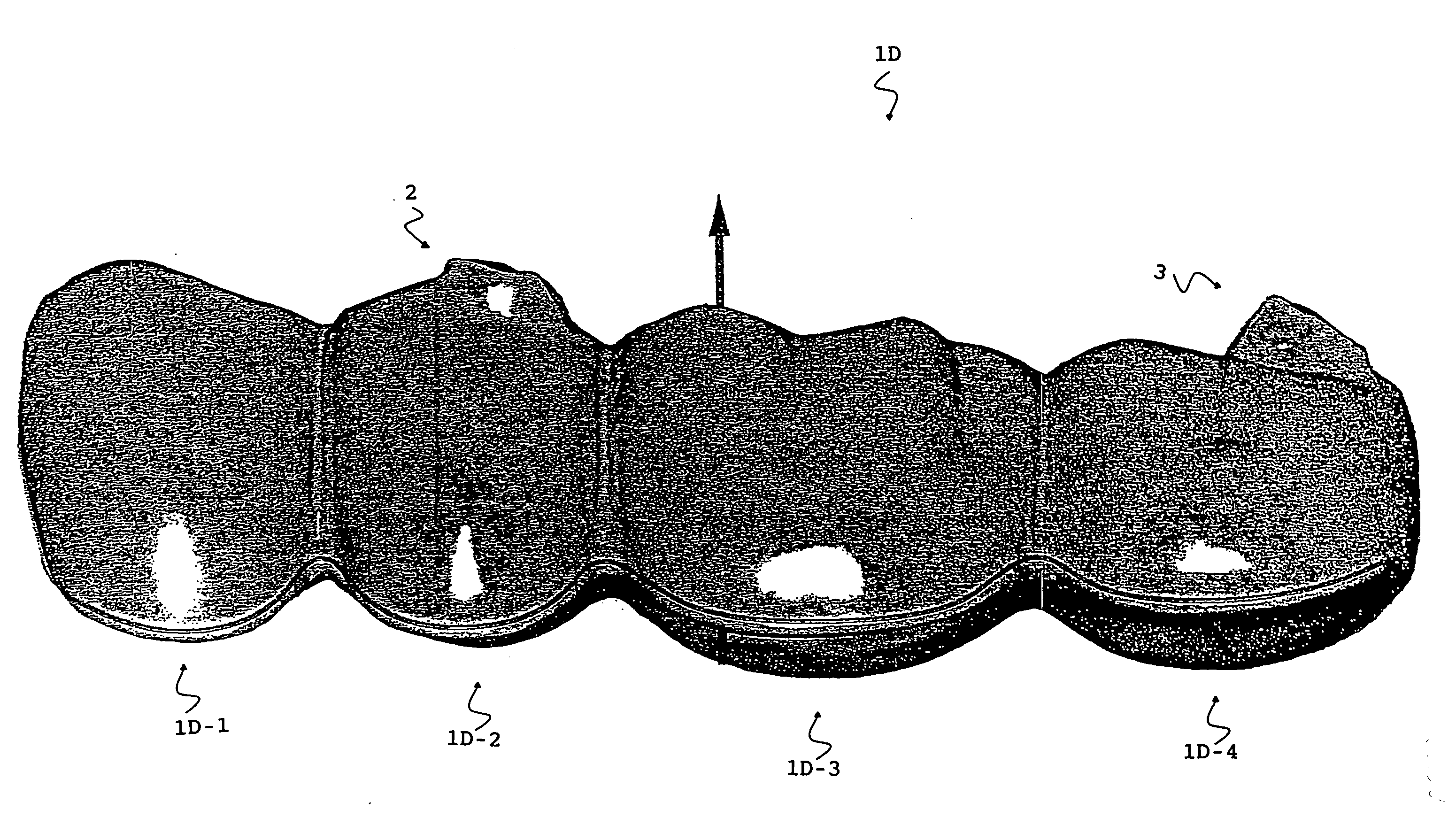
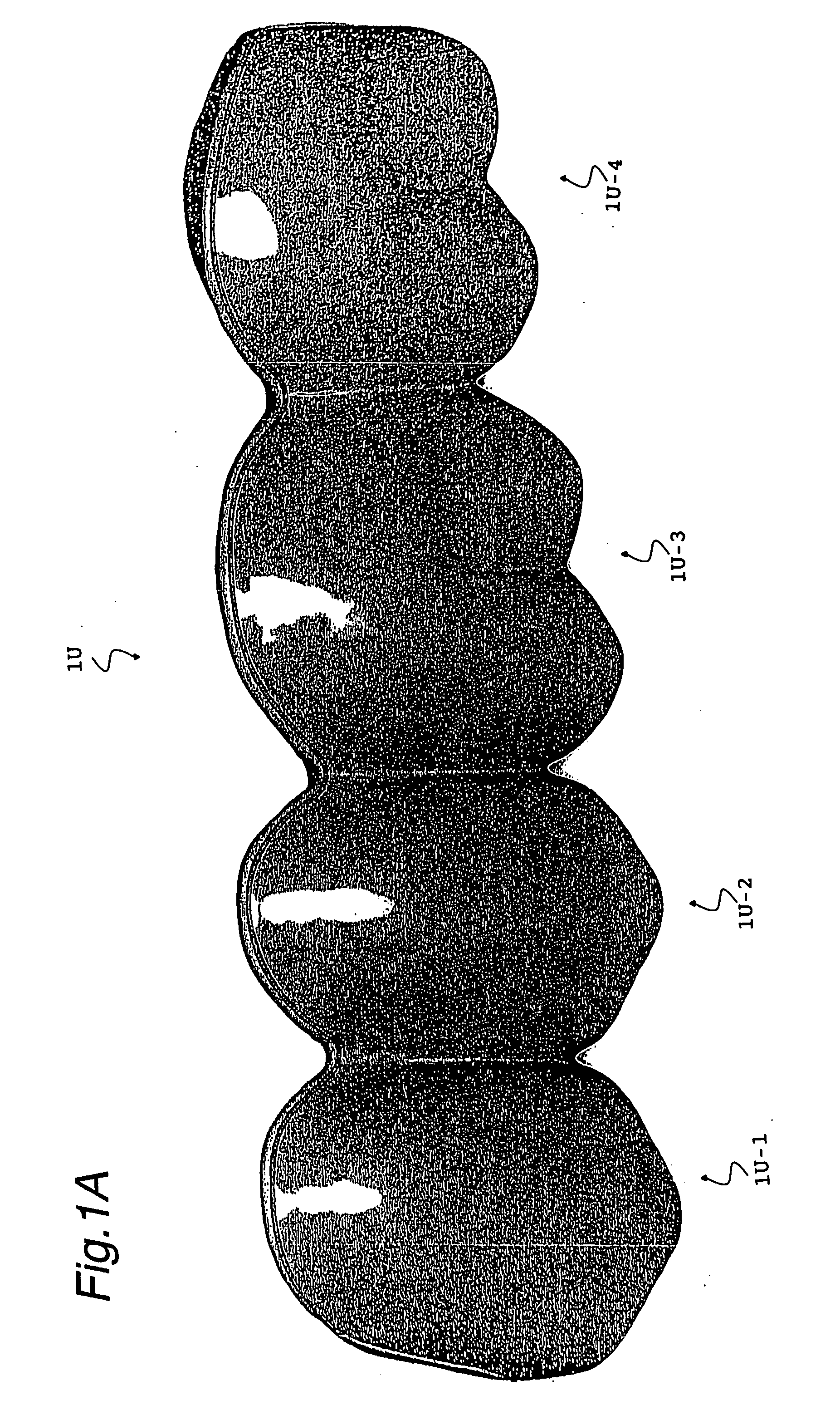
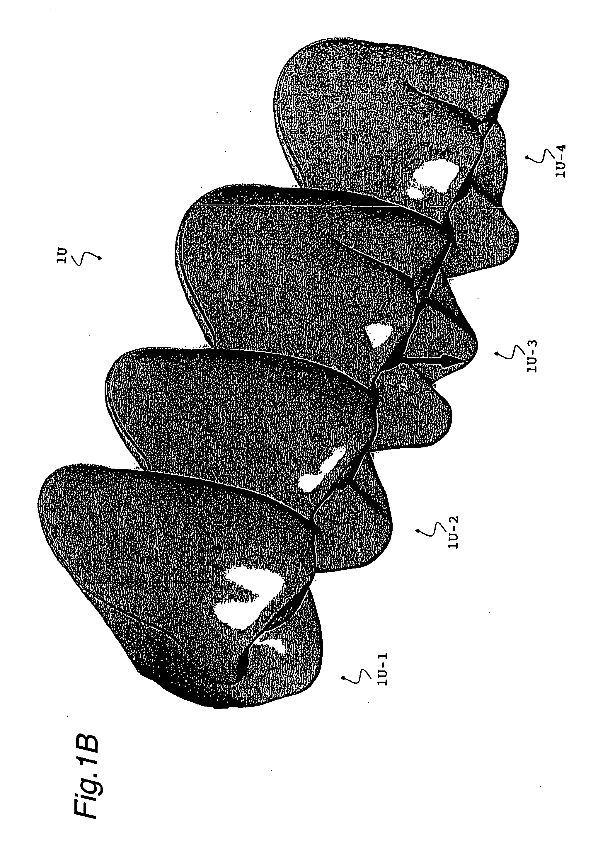
[0050]FIGS. 1A and 1B show, respectively, a dental prosthesis of four interconnected artificial maxillary molars, “1U”, designed for the lingualized occlusion according to an embodiment of the present invention. The dental prosthesis of artificial maxillary molars 1U is made of hard resin, for example, and comprises a first premolar 1U-1, a second premolar 1U-2, a third molar 1U-3 and a fourth molar 1U-4, which are securely interconnected to form the dental prosthesis. It will be appreciated that each of these artificial molars has been arranged such that a mesio-distal position, a bucco-lingual position, a vertical position, a mesio-distal axis of tooth, a bucco-lingual axis of tooth and a degree of torsiversion are in conformity with the aesthetic standard as well as in complying with the general principle of occlusal contact manner in each specific tooth.

[0051] Referring to FIGS. 2A to 2D, there is shown a...


PUM


Abstract

Provided is a dental prosthesis formed as artificial molars designed for a lingualized occlusion, comprising the total of four teeth including a first premolar, a second premolar, a first molar and a second molar in a maxilla or a mandible, which are interconnected in a single prosthesis. An artificial maxillary molar is configured to have a blade form in a lingual cusp thereof, and a protrusion is formed in buccal cusps of a mandibular second premolar and a mandibular second molar so as to define a gap for gliding movement to take place between said artificial mandibular molar and oppositely-located artificial maxillary molars. A groove is formed in a bottom side of the four interconnected artificial molars, said groove extending throughout said four teeth and open at an end of the first premolar and an end of the second molar.

Description

FIELD OF THE INVENTION [0001] The present invention relates to an artificial tooth, a jig for arranging said artificial tooth, an arrangement method of the same and a denture. DESCRIPTION OF THE PRIOR ART [0002] It has been typically required in fabricating a denture in the prior art that a set of artificial teeth is secured to a denture baseplate one at a time and in sequence. When fabricating a complete denture according to the prior art, it has been necessary to determine all of the positions, such as a mesio-distal position, a bucco-lingual position, a vertical position, a mesio-distal axis of tooth, a bucco-lingual axis of tooth and a degree of torsiversion, within a jaw, so as to achieve a required level of functionality and aesthetics of each tooth in the denture, including the teeth in the anterior segment and the sixteen molars of the posterior segment. Before securing each tooth in its position on the denture base plate, a required volume of wax must be softened by heating...

Claims


Application Information

Patent Timeline
IPC IPC(8): A61C13/08A61C13/00A61C13/097A61C13/10
CPCA61C13/097A61C13/0024A61C13/1016A61C13/1006
Inventor KOIDE, KAORU
Owner HERAEUS KULZER JAPAN
Why Eureka
Try Eureka