
Method and system for controlling airfoil actuators

a technology of airfoil actuator and actuator, which is applied in the direction of automatic actuation, process and machine control, instruments, etc., can solve the problem of small number of structures containing a large number o

Inactive Publication Date: 2006-11-30
SYRACUSE UNIVERSITY
View PDF15 Cites 13 Cited by
  • Summary
  • Abstract
  • Description
  • Claims
  • Application Information

AI Technical Summary

Benefits of technology

[0016] It is a principal object and advantage of the present invention to provide a method for using Proper Orthogonal Decomposition and Modified Linear Stochastic Estimation to determine the flow velocity over an airfoil.
[0017] It is an additional object and advantage of the present invention to provide a method for feedback control over airfoil actuator using Proper Orthogonal Decomposition and Modified Linear Stochastic Estimation to determine the flow velocity and a feedback loop.
[0018] Other objects and advantages of the present invention will in part be obvious, and in part appear hereinafter. SUMMARY OF THE INVENTION
[0019] By using a combination of Particle Image Velocimetry PIV and multiple surface pressure measurements, processed through a POD / mLSE algorithm, estimates of the velocity field from wall pressure alone are extracted. From such estimates knowledge of the state of the flow above the airfoil can be obtained (i.e., attached, fully separated or incipiently separated). Integral to the POD / mLSE algorithm is the estimation of the global POD coefficients. The utility of these time dependent coefficients, which are estimated from surface pressure only, are demonstrated in a simple proportional feedback loop (as the time series to drive the actuators) to keep the flow attached. This methodology of the present invention is critical for implementation of realistic feedback flow control since surface measurements and not inflow measurements are required for practical applications. The methodology of the present invention also works well in connection with dynamic strain on flexible bodies, so the approach is not limited to estimation from pressure only.

Problems solved by technology

This results in a small number of the structures containing a large percentage of the system dynamics.

Method used


Image

  • Method and system for controlling airfoil actuators
  • Method and system for controlling airfoil actuators
  • Method and system for controlling airfoil actuators

Examples


example

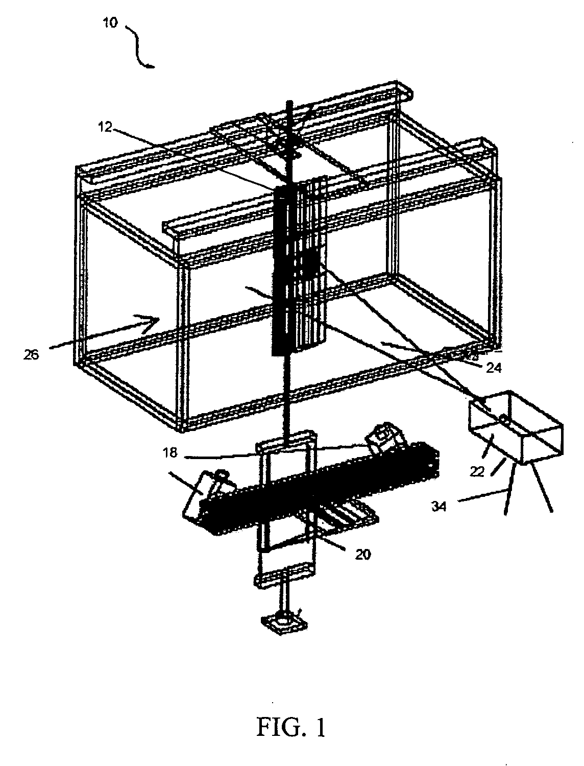
[0050] The present invention was tested in the subsonic wind tunnel facility at Syracuse University, which consists of a Gottingen-type, closed, recirculating design with the flow loop arranged in a horizontal configuration. The test section, 24 in (w)×24 in (h)×96 in (1), was made of optical plexiglass panels and is illustrated with the full experimental test section 10 in FIG. 1. The speed in test section 10 is continuously variable from less than 10 ft / s to greater than 230 ft / s.

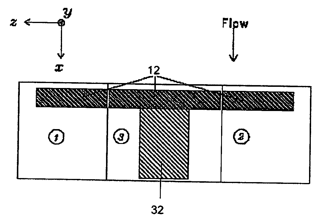
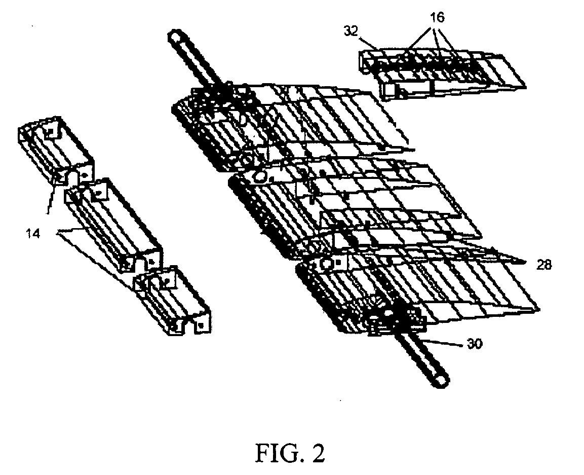
[0051] A NACA 4412 airfoil 12 with an 8 inch chord was selected for the experiments. The test model was designed to meet several requirements. It had two-dimensional with a constant chord length and included an airfoil section geometry along the span. The model size was chosen to avoid significant blockage in the 2 ft.×2 ft. wind tunnel test section. Actuator sections 14 and pressure transducers 16 were configured in a modular fashion to enable rearrangement when required. Three-dimensional effects from ...


PUM


Abstract

A method of measuring the state of flow above an airfoil using an estimation of the velocity field based on a combination of Particle Image Velocimetry PIV and multiple surface pressure measurements processed through a POD / mLSE algorithm. Integral to the POD / mLSE algorithm is the estimation of the global POD coefficients. The utility of these time dependent coefficients, which are estimated from surface pressure only, are demonstrated in a simple proportional feedback loop (as the time series to drive the actuators) to keep the flow attached. This method requires realistic feedback flow control since surface measurements and not inflow measurements are required for practical applications. The estimation method works well with dynamic strain on flexible bodies and is not limited to estimation from pressure only.

Description

CROSS-REFERENCE TO RELATED APPLICATIONS [0001] The present application claims priority to U.S. Provisional Application Ser. No. 60 / 582,113, entitled “Using POD / mLSE algorithms to provide measurement input from surface measurements for driving actuators in active feedback flow control,” filed on Jun. 23, 2004.BACKGROUND OF THE INVENTION [0002] 1. Field of Invention [0003] The present invention relates to airfoil actuator feedback controls and, more specifically, to the use of proper orthogonal decomposition (POD) and modified linear stochastic estimation (mLSE) for the determining the flow velocities over an airfoil and correspondingly controlling the actuators of the airfoil. [0004] 2. Description of Prior Art [0005] The present invention is based on a foundation laid by Taylor, J. A. and Glauser, M. N., 2002, Towards Practical Flow Sensing and Control via POD and LSE Base Low-Dimensional Tools, 2002 ASME Fluids Engineering Division, Summer Meeting, Montreal, ASME Paper FEDSM 2002-3...

Claims


Application Information

Patent Timeline
Patent Type & Authority Applications(United States)
IPC IPC(8): G05D1/06G01M9/00B64C13/16
CPCG01M9/065G01M9/06
Inventor GLAUSER, MARKHIGUCHI, HIROSHI
Owner SYRACUSE UNIVERSITY
Learn More