High plasma utilization for remote plasma clean

a plasma cleaning and plasma technology, applied in the manufacture of tubes/lamp screens, chemistry apparatus and processes, etc., can solve the problems of molecule less efficient than radical cleaning, damage or destruction of substrate components, chamber cleaning using a remote plasma source is often not as efficient,

Inactive Publication Date: 2006-11-30
APPLIED MATERIALS INC
View PDF45 Cites 226 Cited by
  • Summary
  • Abstract
  • Description
  • Claims
  • Application Information

AI Technical Summary

Benefits of technology

[0014] In another embodiment, a method of cleaning a chemical vapor deposition chamber comprises introducing reactive species from a remote plasma source into the chemical vapor deposition chamber through a first inlet configured to provide reactive species from the remote plasma source into a processing region of the chemical vapor deposition chamber via a gas distribution assembly of the chemical vapor deposition chamber, and introducing reactive species from the same or a different remote plasma source into the processing region of the chemical vapor deposition chamber through a second inlet configured to provide reactive species from the same or a different remote plasma source into the processing region of the chemical vapor deposition chamber while bypassing the gas distribution assembly.

Problems solved by technology

This deposited material can flake off during subsequent processing and create contaminating particles that can damage or destroy components of the substrate in the chamber.
It has been observed that chamber cleaning using a remote plasma source is often not as efficient as would be expected based on the estimated dissociation rate provided by the remote plasma source.
Reactive species generated by remote plasma sources can recombine to form molecules that are less efficient in cleaning than the radicals.
Thus, since the pressure of the chamber that receives gases from a remote plasma source with the plasma power turned on is about 50% of the expected pressure, it appears that approximately 50% of the reactive species are lost in the chamber due to recombination of the reactive species.
One cause of recombination is the restricted flow area provided by the gas distribution assembly of chemical vapor deposition chambers.
Low chamber cleaning efficiency resulting from recombination increases the amount of time required to clean a chamber, which reduces the substrate throughput of the chamber and increases the cost of the cleaning gas required to clean the chamber.
The extra cleaning time required to sufficiently clean parts of the chamber, such as the edges and corners of the chamber, can result in damage by overetching to other parts of the chamber.

Method used


Image

  • High plasma utilization for remote plasma clean
  • High plasma utilization for remote plasma clean
  • High plasma utilization for remote plasma clean

Examples


Embodiment Construction

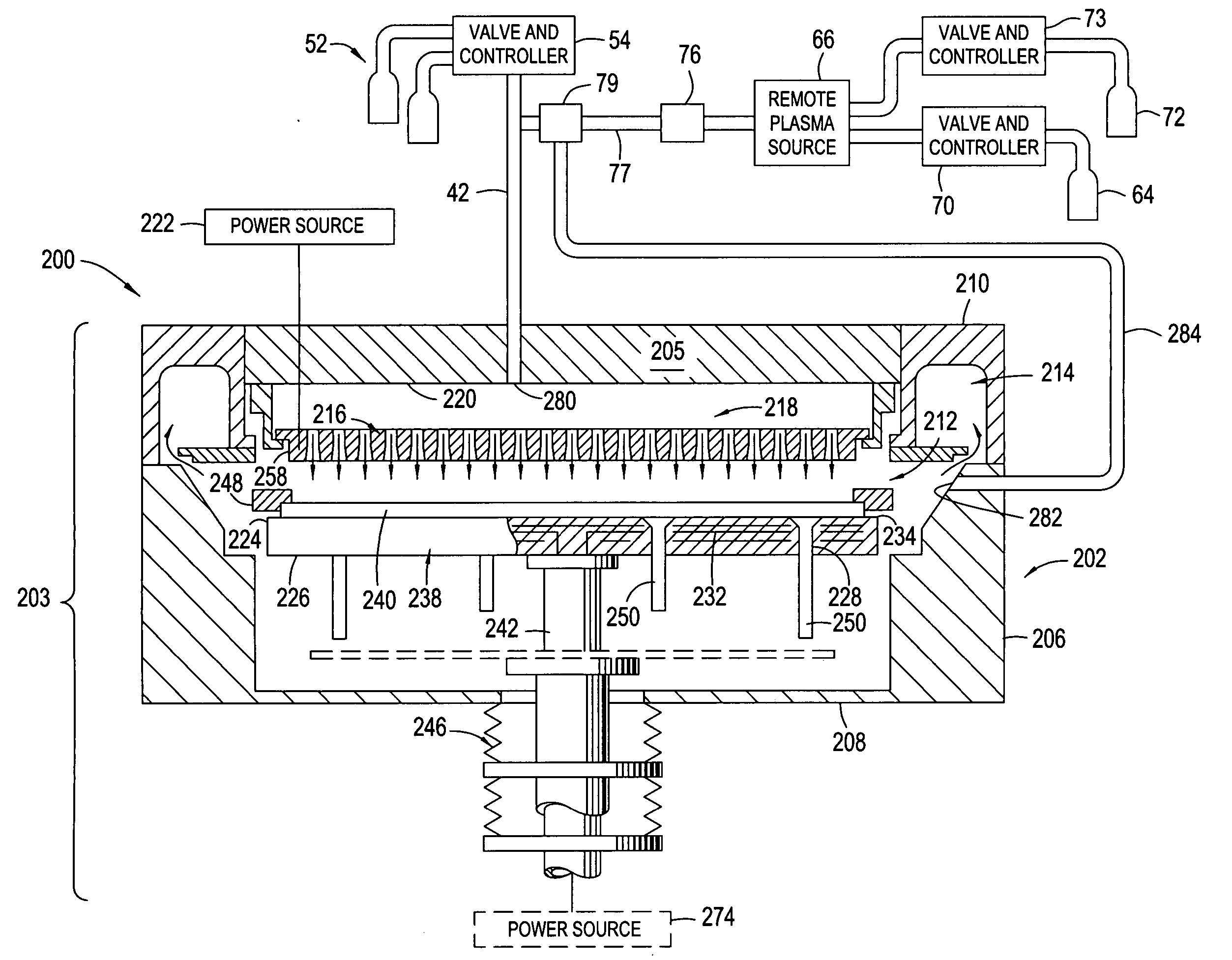
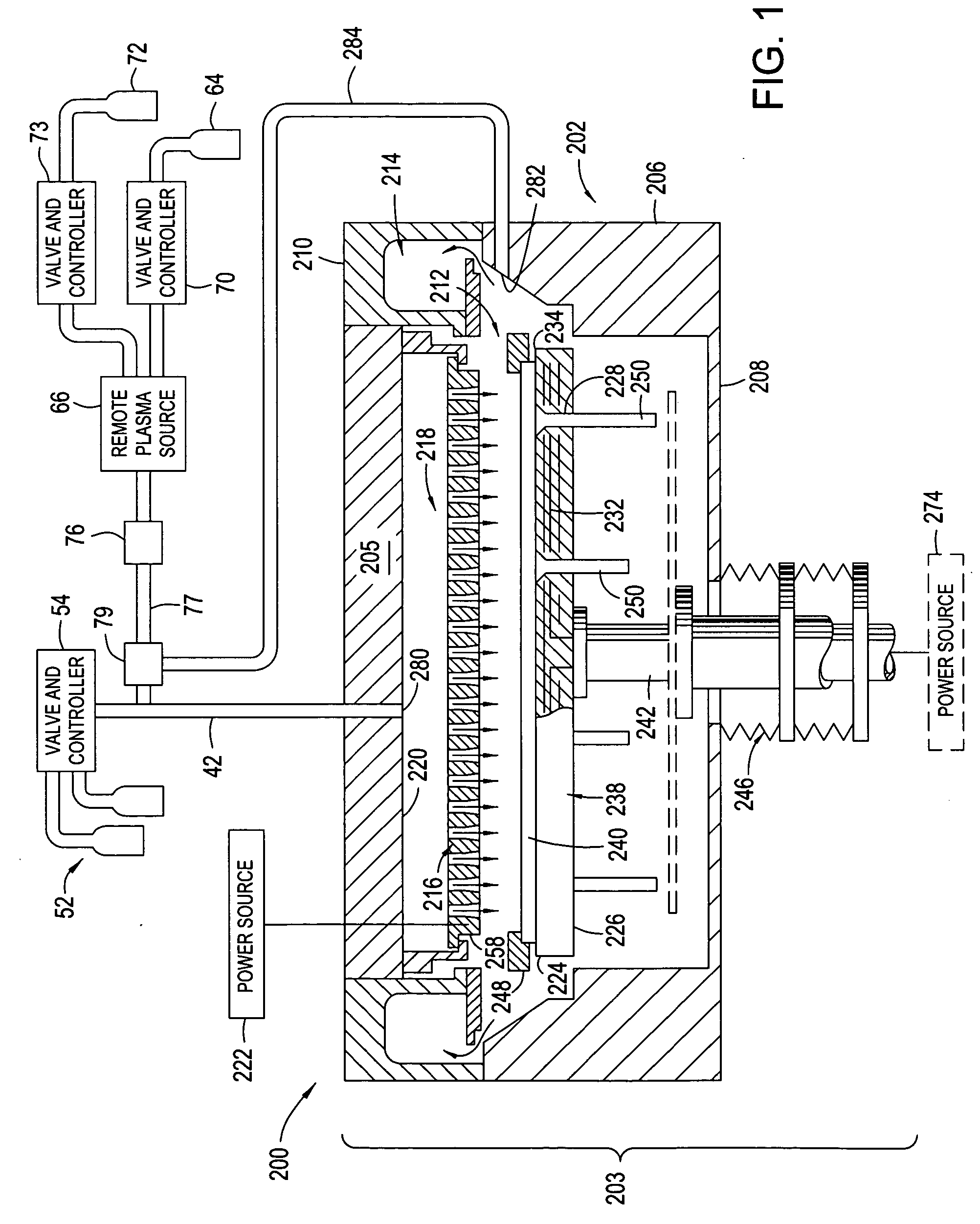
[0020] Embodiments of the present invention provide a chemical vapor deposition system that includes a chemical vapor deposition chamber comprising a first inlet for providing reactive species from a remote plasma source into a processing region of the chamber via a gas distribution assembly of the chamber and a second inlet for providing reactive species from a remote plasma source into the processing region of the chamber without flowing the reactive species through the gas distribution assembly, i.e., while bypassing the gas distribution assembly.

[0021]FIG. 1 is a schematic cross-sectional view of a plasma enhanced chemical vapor deposition system 200 according to an embodiment of the invention. The plasma enhanced chemical vapor deposition system 200 is similar to the plasma enhanced chemical vapor deposition system 4300, which is available from AKT, a division of Applied Materials, Inc., of Santa Clara, Calif. Other systems that may be modified according to embodiments of the ...


PUM

PropertyMeasurementUnit
thicknessaaaaaaaaaa
diameteraaaaaaaaaa
pressureaaaaaaaaaa

Abstract

A method and apparatus for cleaning a chemical vapor deposition chamber are provided. The chemical vapor deposition chamber includes an inlet that introduces reactive species into the chamber from a remote plasma source while bypassing a gas distribution assembly of the chamber and an inlet that introduces reactive species from a remote plasma source into the chamber via the gas distribution assembly.

Description

BACKGROUND OF THE INVENTION [0001] 1. Field of the Invention [0002] Embodiments of the present invention generally relate to a method of cleaning a chemical vapor deposition chamber. In particular, embodiments of the invention relate to a method of cleaning a chemical vapor deposition chamber for processing large area substrates. [0003] 2. Description of the Related Art [0004] Chemical vapor deposition (CVD) is a commonly used method of depositing materials to form layers on substrates during the manufacture of integrated circuits and semiconductor devices. Chemical vapor deposition is typically performed by delivering gases to a substrate supported on a substrate support in a chemical vapor deposition chamber. The gases are delivered to the substrate through a gas distribution assembly in the chamber. [0005] During chemical vapor deposition, deposited material is also formed on components of the chamber, such as the gas distribution assembly and the internal sidewalls of the chambe...

Claims


Application Information

Patent Timeline
Patent Type & Authority Applications(United States)
IPC IPC(8): C23C16/00B08B6/00
CPCC23C16/4405H01J37/3244H01J9/20
Inventor CHOI, SOO YOUNG
Owner APPLIED MATERIALS INC
Why Eureka
Try Eureka