Device and a method for selective control of fluid flow between a well and surrounding rocks

a fluid flow and well technology, applied in drinking water installation, wellbore/well accessories, etc., can solve the problems of difficult or impossible selectively opening one or several specific flow apertures in the flow pipe at different moments of time, difficult or impossible selectively determining, unfavourable pressure- and flow pattern, etc., and achieves small operational flexibility

Inactive Publication Date: 2006-11-30
RESLINK
View PDF8 Cites 22 Cited by
  • Summary
  • Abstract
  • Description
  • Claims
  • Application Information

AI Technical Summary

Benefits of technology

[0014] The primary object of the invention is to avoid or reduce the above-mentioned disadvantages of prior art. The specific object of the invention is to render possible, during a period of time, selective control of fluid flow paths between a flow pipe of a sand-screen-provided well and surrounding rocks. Thus, and by means of separate well intervention, inflow or outflow positions along the flow pipe may be opened or shut off selectively and timely, thereby achieving optimum flow paths into or out of the well.
[0023] Thus, the fluid flow paths between the well and surrounding rocks may be controlled selectively and timely. The performance and utilization of the well and the rocks surrounding it thus is improved appreciably. In connection with installation of the flow pipe in the well, also external pipe packers of known types are utilized to isolate such sand screens and associated rock zones from other sand screens and rock zones.
[0024] In horizontal wells and highly deviated wells, such an imperforated and sand-screen-provided flow pipe provides a further advantage. In such wells, it may be problematic to introduce a common pre-perforated flow pipe into the horizontal or highly deviated section of the well, mostly due to friction between the borehole and the flow pipe. However, when the flow pipe is imperforated, and its lower end portion is blinded off, the flow pipe may be filled with a suitable fluid, for example nitrogen gas, providing the pipe with a buoyancy effect, which reduces said friction. Then the pipe may be floated onwards to a desired well depth, upon which said fluid is released from the pipe.

Problems solved by technology

However, the production tubing according to U.S. Pat. No. 5,526,881 is not provided with a sand screen.
A substantial disadvantage of all the above-mentioned, prior art isolation solutions is that it is difficult or impossible to selectively open one or several specific flow apertures in the flow pipe at different moments of time.
Thus, it is difficult or impossible to selectively determine, hence control, the fluid flow paths between the flow pipe of the well and the surrounding rock zones during a recovery period or injection period.
This may easily result in an unfavourable pressure- and flow pattern in the well and / or in the surrounding rocks.
Prior art isolation solutions therefore exhibit a relatively small operational flexibility.
Any re-completion or opening of one or several of said other rock zones at a later point in time usually will require a relatively complex, comprehensive and expensive intervention operation.
Also, the above-mentioned, prior art metal plugs or sealing agent will not withstand large pressure differentials that may exist between the inside and outside of the flow pipe, whereby they unintentionally may burst and disintegrate.
Due to the pipe string being subjected to tensile extension while in position of use, however, this method may be too inaccurate for this purpose.
In such wells, it may be problematic to introduce a common pre-perforated flow pipe into the horizontal or highly deviated section of the well, mostly due to friction between the borehole and the flow pipe.

Method used


Image

  • Device and a method for selective control of fluid flow between a well and surrounding rocks
  • Device and a method for selective control of fluid flow between a well and surrounding rocks
  • Device and a method for selective control of fluid flow between a well and surrounding rocks

Examples


Embodiment Construction

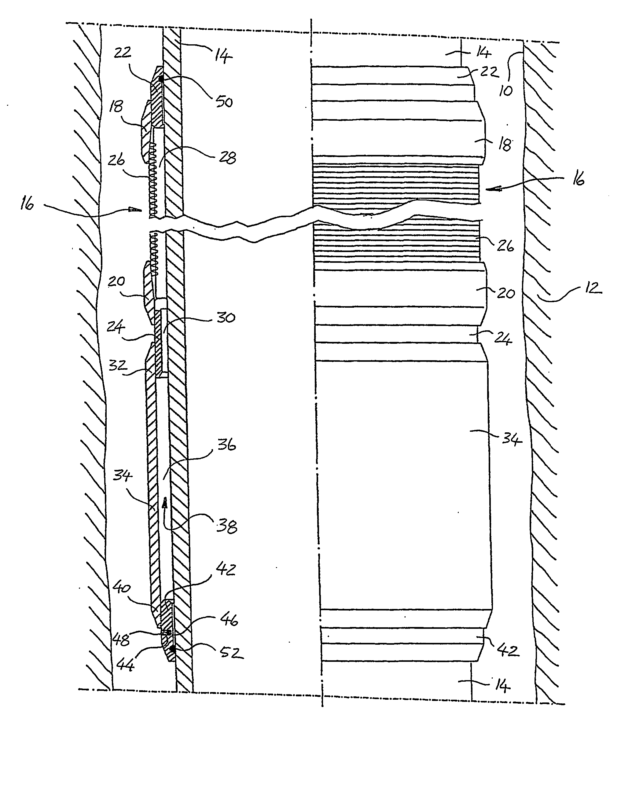
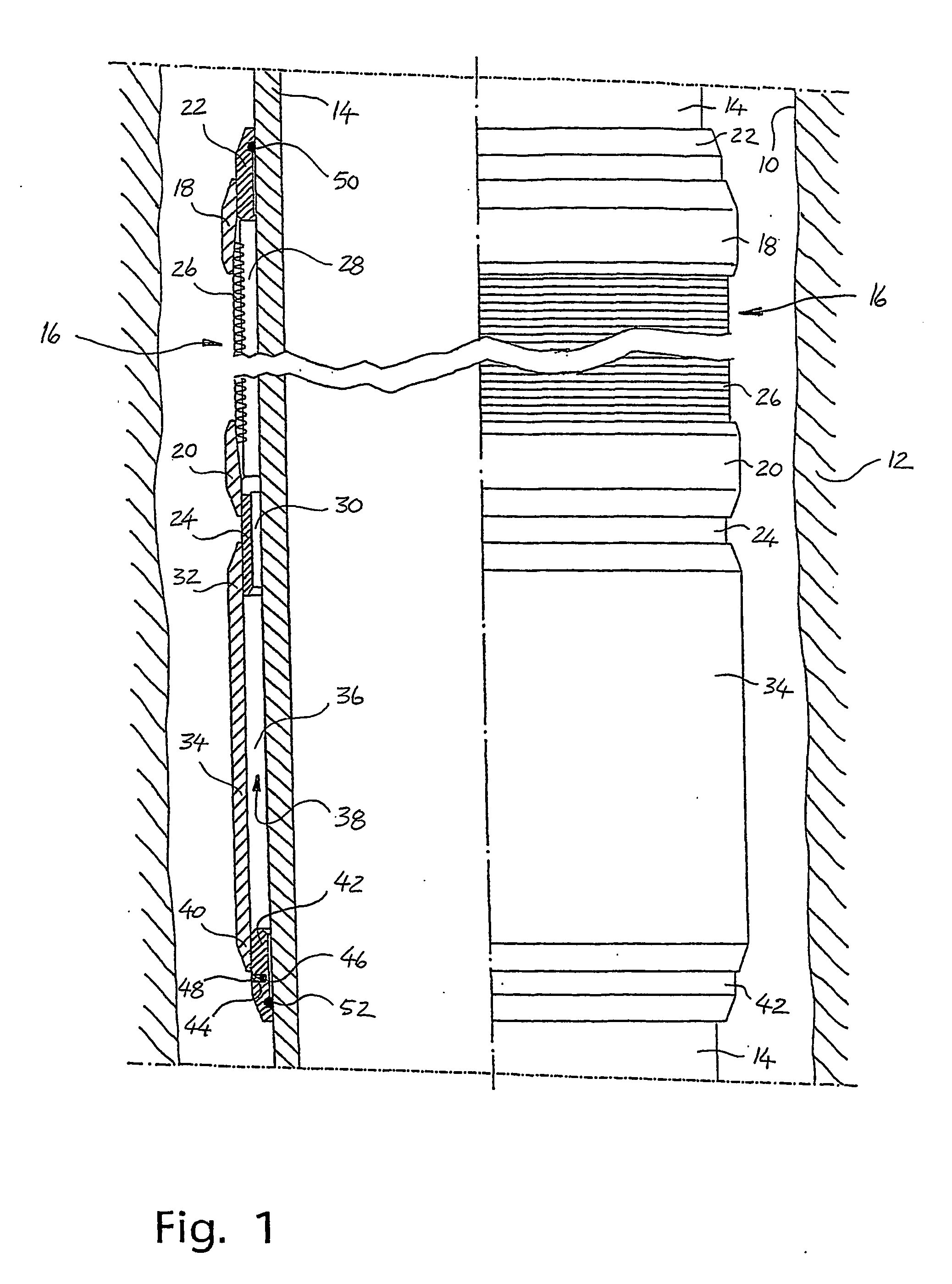
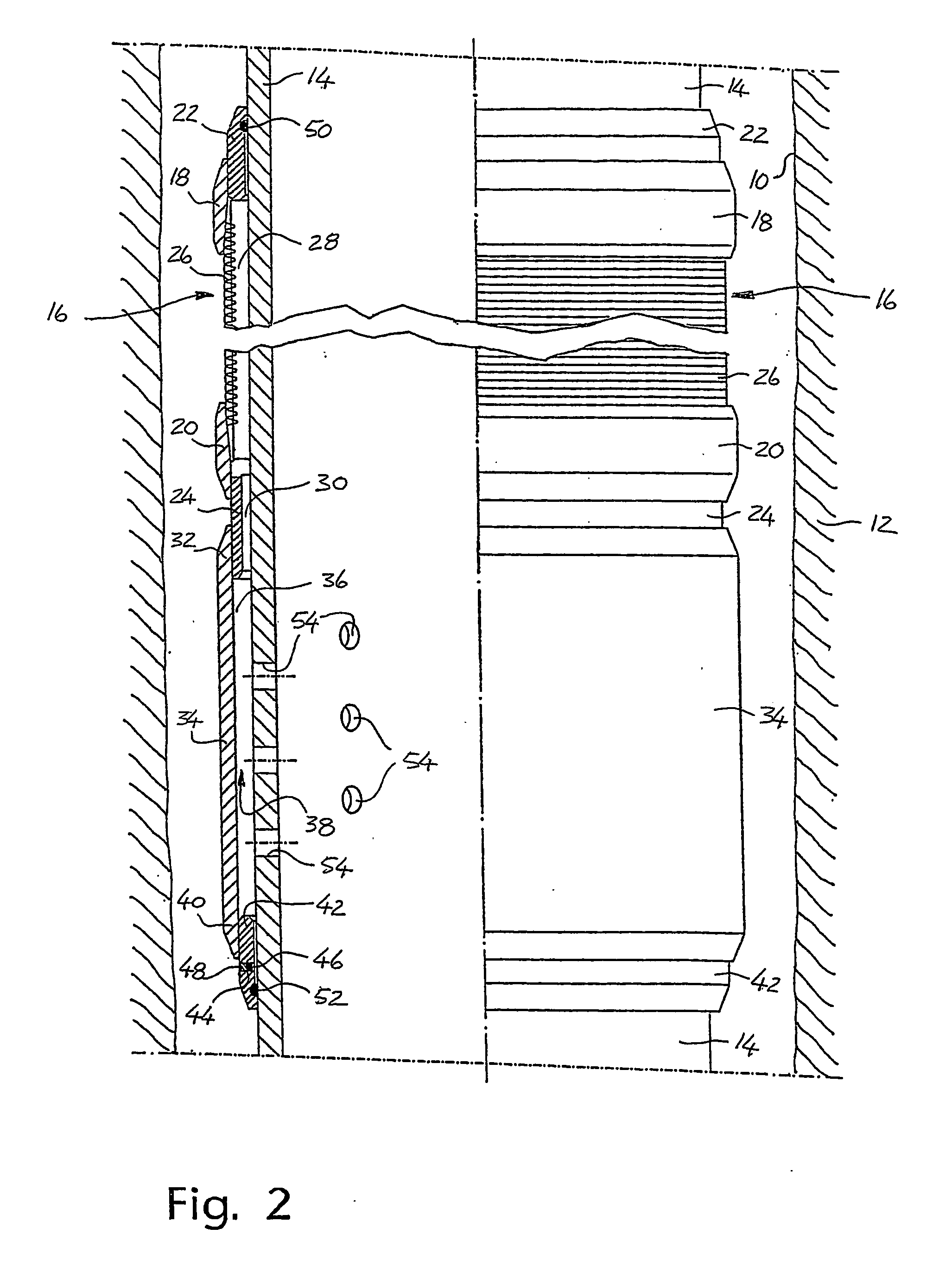
[0027]FIG. 1 shows a section of a horizontal portion of an uncased borehole 10 of a production well, in which said horizontal portion penetrates a reservoir rock 12. The figure shows a base pipe 14 of the production tubing of the well, the production tubing being placed in the borehole 10 and extending up to the surface.

[0028] At least one base pipe 14 of the production tubing is provided with an external sand screen 16 affixed, by means of outer shrink rings18, 20, on the outside of an inner shrink ring 22 and a connection ring 24, respectively, both of which are connected to the base pipe 14. Only the end portions of the sand screen 16 are shown in the figures.

[0029] The filter medium in the sand screen 16 consists of wire windings 26 wound on the outside of axial lists (not shown) on the base pipe 14, a ring-shaped filter chamber 28 thereby existing between the windings 26 and the pipe 14.

[0030] The connection ring 24 is provided with an inner, ring-shaped passage 30 being ope...


PUM


Abstract

A device and a method for selective control of fluid flow between a flow pipe (14) of a well and surrounding rocks (12). The flow pipe (14) is provided with at least one flow-through particle filter (16) placed externally on the flow pipe (14) and between the flow pipe (14) and the rocks (12). The filter (16) is connected in a flow-through manner to the flow pipe (14) via a flow channel (38). The characteristic of the invention is that the flow pipe (14) is provided with an imperforated pipe wall inside of and vis-a-vis said flow channel (38) when installing the flow pipe (14) in the well. Then the flow pipe (14) may be perforated selectively inside of the flow channel (38) for one or several filters (16) along the flow pipe (14), whereupon fluids may flow through the flow channel (38) and the filter (16) via perforation apertures (54) in the flow pipe (14).

Description

FIELD OF INVENTION [0001] This invention concerns a device and a method for selectively controlling flow path(s) of fluids between a well and surrounding subsurface rocks. Said fluids flow via at least one filter, for example a sand screen, arranged between the flow pipe and the surrounding rocks. Said at least one filter prevents solid particles from entering the well, and the filter hereinafter is denoted a sand screen only. [0002] Preferably, the well is provided with a so-called open-hole completion, in which the flow pipe of the well is arranged in an open and uncased borehole. Alternatively, the well may be provided with cemented and perforated casings within which the flow pipe of the well is placed. Thus, said fluids flow via both said filter and perforations in the cemented casings. [0003] Preferably, the present invention is used in connection with petroleum recovery and preferably in connection with production of reservoir fluids, including crude oil and / or gas. Moreover,...

Claims


Application Information

Patent Timeline
Patent Type & Authority Applications(United States)
IPC IPC(8): E21B43/00E21B43/119E21B43/12
CPCE21B43/12E21B43/119
Inventor DYBEVIK, ARTHUR H.
Owner RESLINK
Why Eureka
Try Eureka