Equipment dryer

Inactive Publication Date: 2006-11-30
PERRY ALAN J
View PDF8 Cites 2 Cited by
  • Summary
  • Abstract
  • Description
  • Claims
  • Application Information

AI Technical Summary

Benefits of technology

[0022] The unit can also be hung (temporarily) onto two nails positioned one over the other in a wall stud. For this, the rack has two larger diameter nail hanging holes. This makes it simple to mount the rack at that location, but also simple to take it down from the wall for travel.
[0023] The free-standing option, which is the usual portable option, makes the rack especially versatile. The three snap-in pins are removed so the A-frame can be disassembled, making it much more compact and easier to transport. These pins are leashed with a nylon fastener to keep them attached to the frame so they stay with the unit and are not lost. The rack can then be placed into a nylon carry bag, which may have a shoulder strap. This is typically the same bag where items of the athletic equipment are also kept. The bag containing the dryer rack can now be easily transported in a vehicle or simply carried over the shoulder. The rack is durable, lightweight, and compact.
[0024] When the athlete arrives at the destination he or she is visiting, the rack is removed from the bag and can be easily assembled, using the snap-in pins, placing the left and right legs and the cross bar back into an A-frame. The pins lock the pieces together. The pieces have ends that are half the thickness of the remainder of the pieces. When the two pieces are placed together, they can only be assembled one way, and make a tight fitting connection. The third leg is then inserted into the back

Problems solved by technology

To date, there have been no convenient wall-mounted drying racks for lacrosse equipment, football equipment, hockey equipment or the like.
There have been sev

Method used


Image

  • Equipment dryer
  • Equipment dryer
  • Equipment dryer

Examples


Embodiment Construction

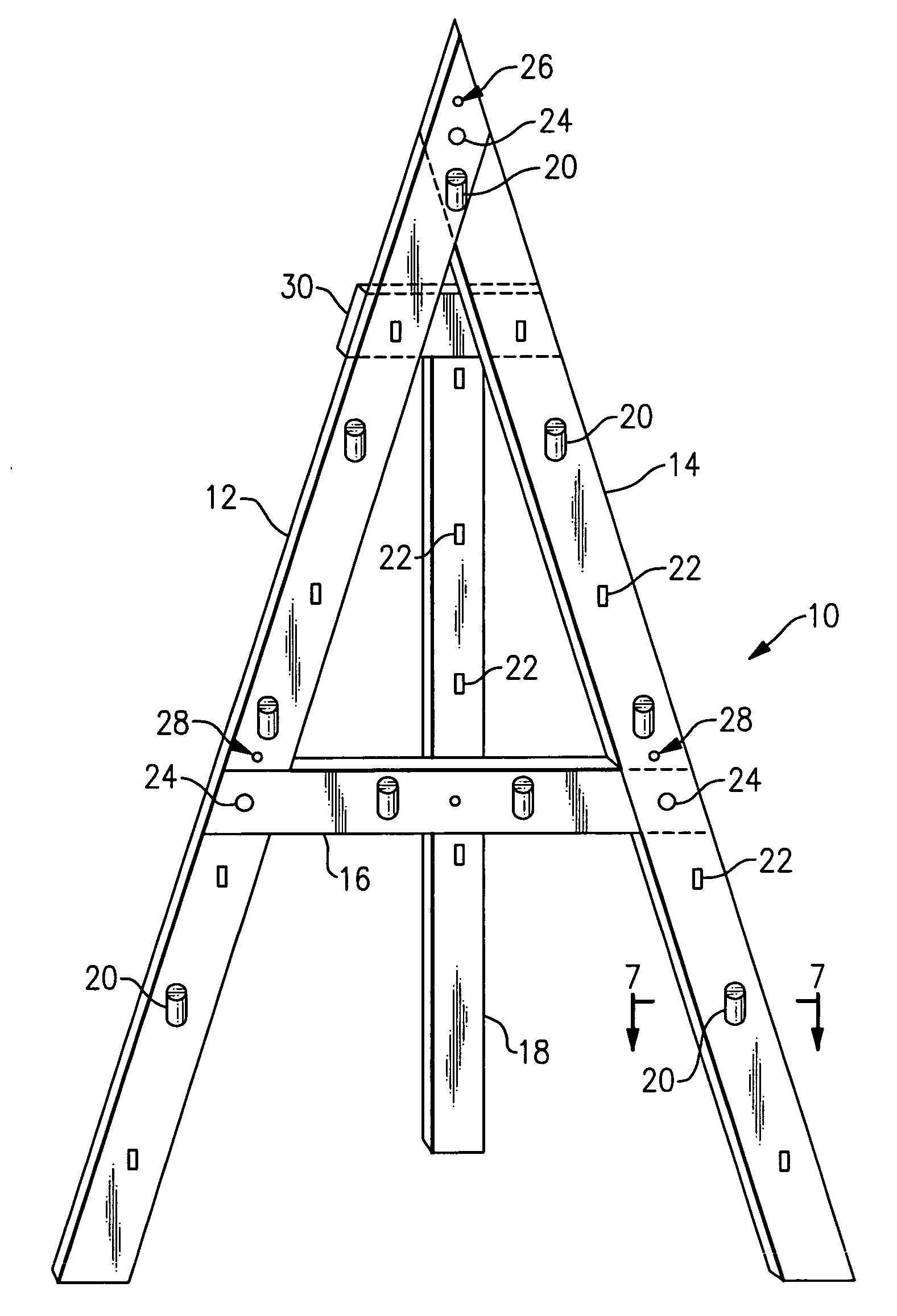
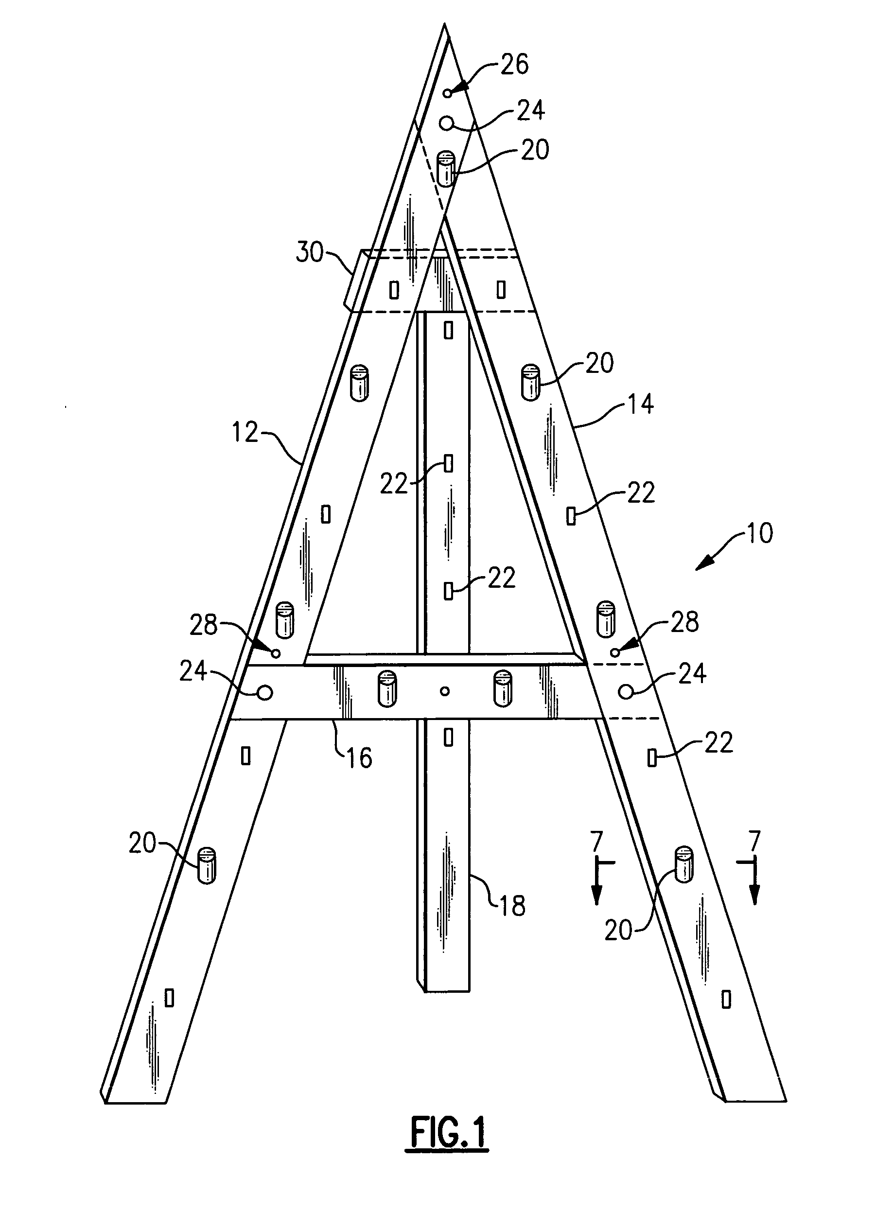
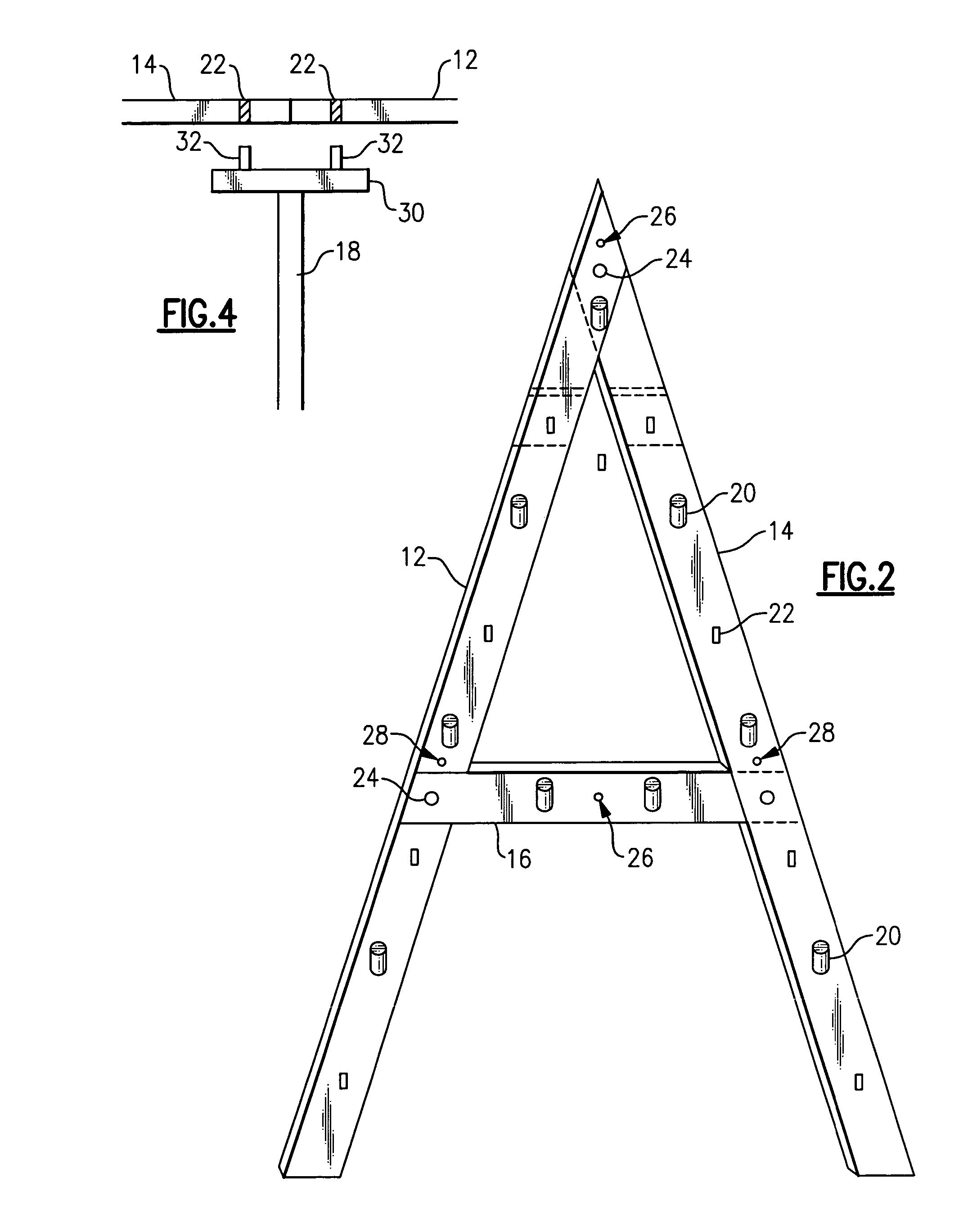
[0038] With reference now to the Drawing, and initially to FIG. 1 a portable drying rack 10 is shown in a front perspective, and is generally in the form of an A-frame, with left and right legs 12, 14 that are spread apart at the base and are joined at an apex, and a generally horizontal cross-arm or cross-bar 16 that joins the two legs at a position just below the center (considered from top to bottom). The preferred embodiment as shown may be supported on a floor or horizontal surface, or may be mounted onto a vertical surface, such as a wall. In the floor or free-standing configuration, as shown, a third or rear leg 18 is attached to the two other legs 12, 14 at or near the apex, and forms a three-legged or tripod assembly. The top or head 30 of the rear leg 18 can be easily inserted or detached, as described below.

[0039] There are a number of removable pegs 20 that can be placed at positions on the side legs 12, 14, the cross-arm 16, and on the rear leg 18 and there provide pla...


PUM


Abstract

An equipment drying rack for athletic gear has the form of an A-frame with left and right legs that meet at an apex, and a cross arm. These are joined with removable snap-in pins, so the rack can be quickly assembled and taken down, and stuffed compactly into a bag for travel. The rack can be wall mounted or a back leg can be installed for free-standing floor use. Hanging pegs can be removably plugged into sockets on the side legs, cross arm, and back leg.

Description

[0001] This application claims priority of U.S. Provisional Application No. 60 / 683,084, filed May 23, 2005.BACKGROUND OF THE INVENTION [0002] This invention concerns a drying rack for holding athletic equipment or other garments and the like to permit drying by air circulation, and is more particularly concerned with a drying rack of a simple design that can be permanently wall mounted, temporarily wall mounted, floor mounted, or taken down into compact form for portability. [0003] The invention is more particularly directed to an equipment air drying rack for drying of athletic equipment, but may also be used for protective garments for outdoor or industrial use, i.e., by athletes, factory workers, outdoor workers, or any of a variety of others. [0004] To date, there have been no convenient wall-mounted drying racks for lacrosse equipment, football equipment, hockey equipment or the like. There have been several proposed versions of portable drying equipment, but these lack compact...

Claims


Application Information

Patent Timeline
IPC IPC(8): E05B73/00
CPCA63B71/00A63B2057/0093F26B25/18D06F59/00A63B2220/76A63B2057/605
Inventor PERRY, ALAN J.
Owner PERRY ALAN J
Why Eureka
Try Eureka