Liquid crystal display device having light shielding sheet

a technology liquid crystal display device, which is applied in non-linear optics, instruments, optics, etc., can solve the problems of difficult release of light shielding sheet from optical sheet and plastic frame, and affecting the quality of images with little power

Inactive Publication Date: 2006-11-30
INNOLUX CORP
View PDF4 Cites 9 Cited by
  • Summary
  • Abstract
  • Description
  • Claims
  • Application Information

AI Technical Summary

Problems solved by technology

Liquid crystal displays are commonly used as display devices for compact electronic apparatuses, because they not only provide good quality images with little power but are also very thin.
In disassembly, it is difficult to release the light shielding sheet from the optical sheet and the plastic frame because of the strength of the adhesive bond of the light shielding sheet.
Thus the optical sheet and the plastic frame are liable to be damaged.
The adhesive of the light shielding sheet may bend when subjected to high temperatures, which can result in a so-called waving phenomena of the light shielding sheet occurring.
When this happens, if the light shielding sheet is not replaced, the optical performance of the liquid crystal display device may be diminished.
One the other hand, if the light shielding sheet is replaced, this is problematic as described above.

Method used


Image

  • Liquid crystal display device having light shielding sheet
  • Liquid crystal display device having light shielding sheet
  • Liquid crystal display device having light shielding sheet

Examples


first embodiment

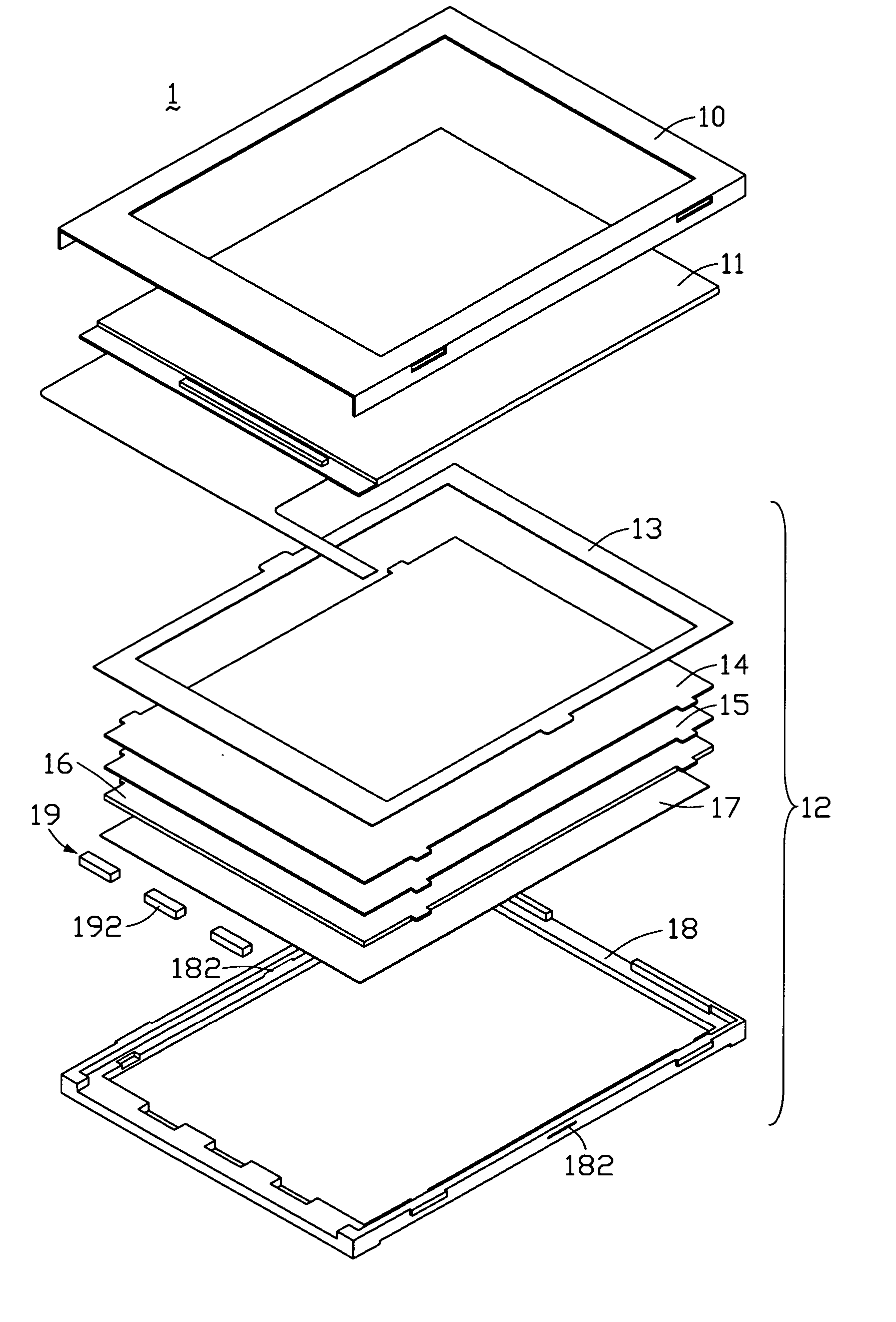
[0016]FIG. 1 is a schematic, isometric view of a liquid crystal display device according to the present invention. The liquid crystal display device 1 includes a first frame 10, a liquid crystal panel 11, and a backlight module 12 in that order from top to bottom. The backlight module 12 includes a light shielding sheet 13, a prism sheet 14, a diffusing sheet 15, a light guide plate 16, a reflective sheet 17, and a second frame 18 in that order from top to bottom. The backlight module 12 further includes a light source 19 disposed adjacent to an end edge of the light guide plate 16. The liquid crystal panel 11 and the backlight module 12 can be accommodated in the first frame 10.

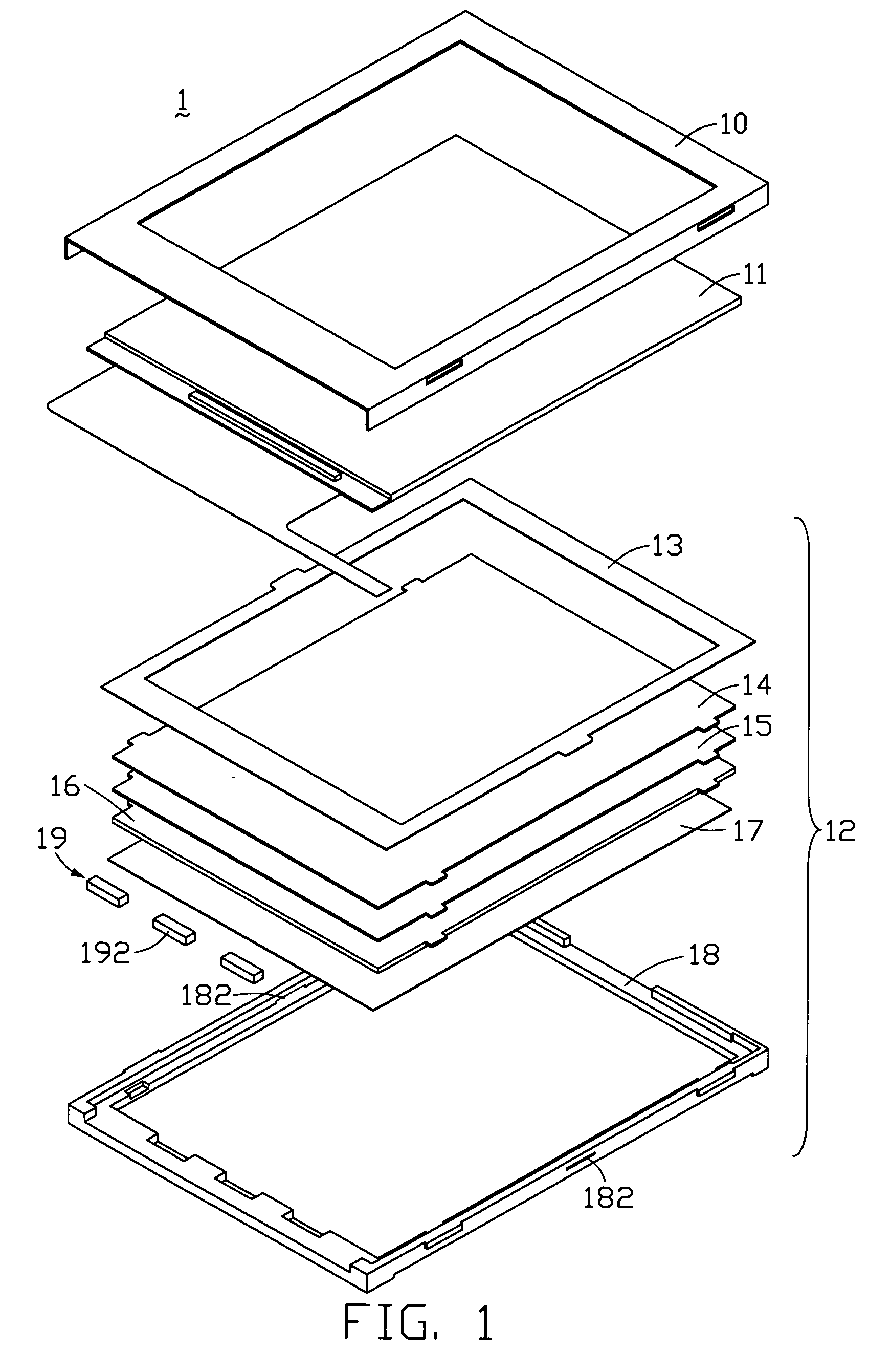
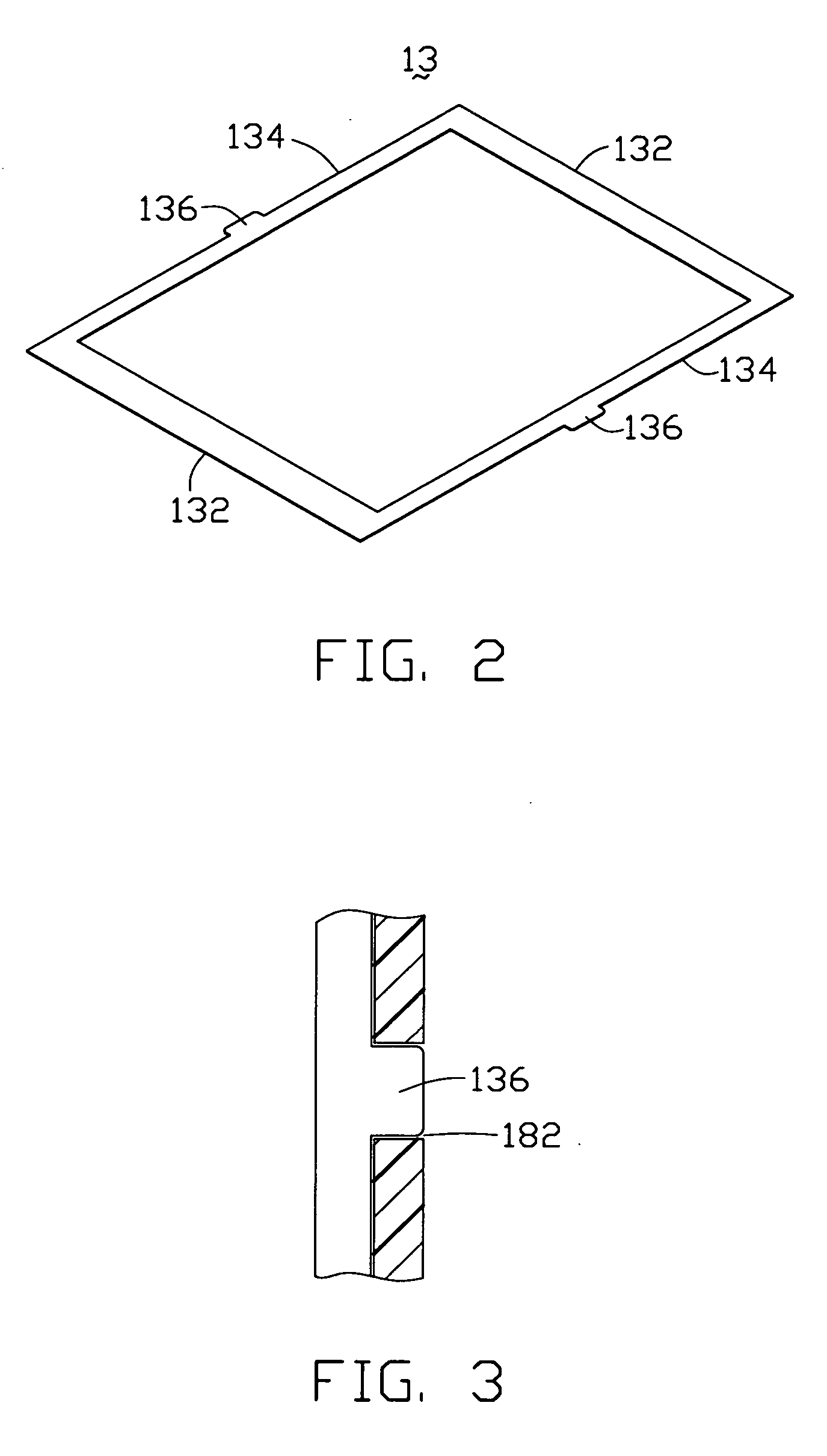
[0017] Referring to FIG. 2, the light shielding sheet 13 is a generally rectangular frame made of elastic material, and includes a pair of opposite outer walls 132 and another pair of opposite outer walls 134. Each outer wall 134 includes a rectangular protrusion 136 at a middle portion thereof. The protrusi...

second embodiment

[0021]FIG. 4 is a schematic, isometric view of a light shielding sheet of a liquid crystal display device according to the present invention. The light shielding sheet 23 is similar to the light shielding sheet 13. However, two opposite outer walls 234 of the light shielding sheet 23 each include two protrusions 236 integrally extending in a direction away from a central long axis (not shown) of the light shielding sheet 23. A frame (not shown) of the liquid crystal display device includes a plurality of holes (not shown), respectively corresponding to the protrusions 236 of the light shielding sheet 23.

third embodiment

[0022]FIG. 5 is a schematic, isometric view of a light shielding sheet of a liquid crystal display device according to the present invention. The light shielding sheet 33 is similar to the light shielding sheet 13, except that the light shielding sheet 33 includes three protrusions 336. One outer wall 332 of the light shielding sheet 33 includes a protrusion 336 integrally extending therefrom, and another outer wall 334 opposite to the outer wall 332 includes two protrusions 336 integrally extending therefrom.


PUM

PropertyMeasurementUnit
temperatureaaaaaaaaaa
strengthaaaaaaaaaa
stabilityaaaaaaaaaa

Abstract

An exemplary liquid crystal display device (1) includes a liquid crystal panel (11) and a backlight module (12) disposed adjacent to the liquid crystal panel. The backlight module includes a frame (18) having a plurality of holes (182), an optical sheet (14) disposed in the frame, and a light shielding sheet (13) disposed between the liquid crystal panel and the optical sheet. The light shielding sheet is frame-shaped, and includes a plurality of outer walls (134) having a plurality of protrusions (136) formed on the outer walls. The protrusions are respectively corresponding to the holes of the frame, and each of the protrusions extends in a direction away from a center of the light shielding sheet. The liquid crystal display device is convenient for disassembly and can avoid a waving phenomena caused by an adhesive used in a conventional liquid crystal display device.

Description

FIELD OF THE INVENTION [0001] The present invention relates to liquid crystal display devices (LCDs), and more particularly to a liquid crystal display device having a light shielding sheet. GENERAL BACKGROUND [0002] Liquid crystal displays are commonly used as display devices for compact electronic apparatuses, because they not only provide good quality images with little power but are also very thin. [0003] A light shielding sheet is generally used in a liquid crystal display device to prevent light beams from leaking out of the display device. The light shielding sheet is generally in the form of a rectangular frame that includes an adhesive thereon. In use, the light shielding sheet is adhesively covered on edges of an optical sheet and a plastic frame that accommodates the optical sheet. [0004] However, the assembly comprising the light shielding sheet, the optical sheet and the plastic frame may need to be disassembled; for example, in order to replace the optical sheet with a...

Claims


Application Information

Patent Timeline
Patent Type & Authority Applications(United States)
IPC IPC(8): G02F1/1333G02F1/13
CPCG02F1/133308G02F2001/133317G02F1/133608G02F1/133317
Inventor YU, CHIH-CHIACHANG, CHENG-FANG
Owner INNOLUX CORP
Why Eureka
Try Eureka