
Impurity-based electroluminescent waveguide amplifier and methods for amplifying optical data signals

an electroluminescent waveguide amplifier and amplifier technology, applied in the field of optical fiber telecommunications systems, can solve the problems of high er concentration, high gain, and compact structure of edfas, and achieve the effect of high gain

Inactive Publication Date: 2006-11-30
UNIVERSITY OF CINCINNATI
View PDF7 Cites 9 Cited by
  • Summary
  • Abstract
  • Description
  • Claims
  • Application Information

AI Technical Summary

Benefits of technology

The electroluminescent waveguide amplifier (ELWA) is a new type of amplifier that uses electrical excitation to achieve high gains, instead of relying on a separate optical pumping source. The gain medium of the ELWA is a simple amorphous thin film coating, which can be easily fabricated without the need for advanced epitaxial growth techniques. The host material of the ELWA can be electrically pumped, eliminating the need for an optical pump source. The host material has a refractive index suitable for a waveguide core, is compatible with a waveguide cladding material, and can produce emission from embedded rare earth ions or other luminescent dopants. Overall, the ELWA is a more compact and efficient amplifier than conventional EDFAs and EDWAs.

Problems solved by technology

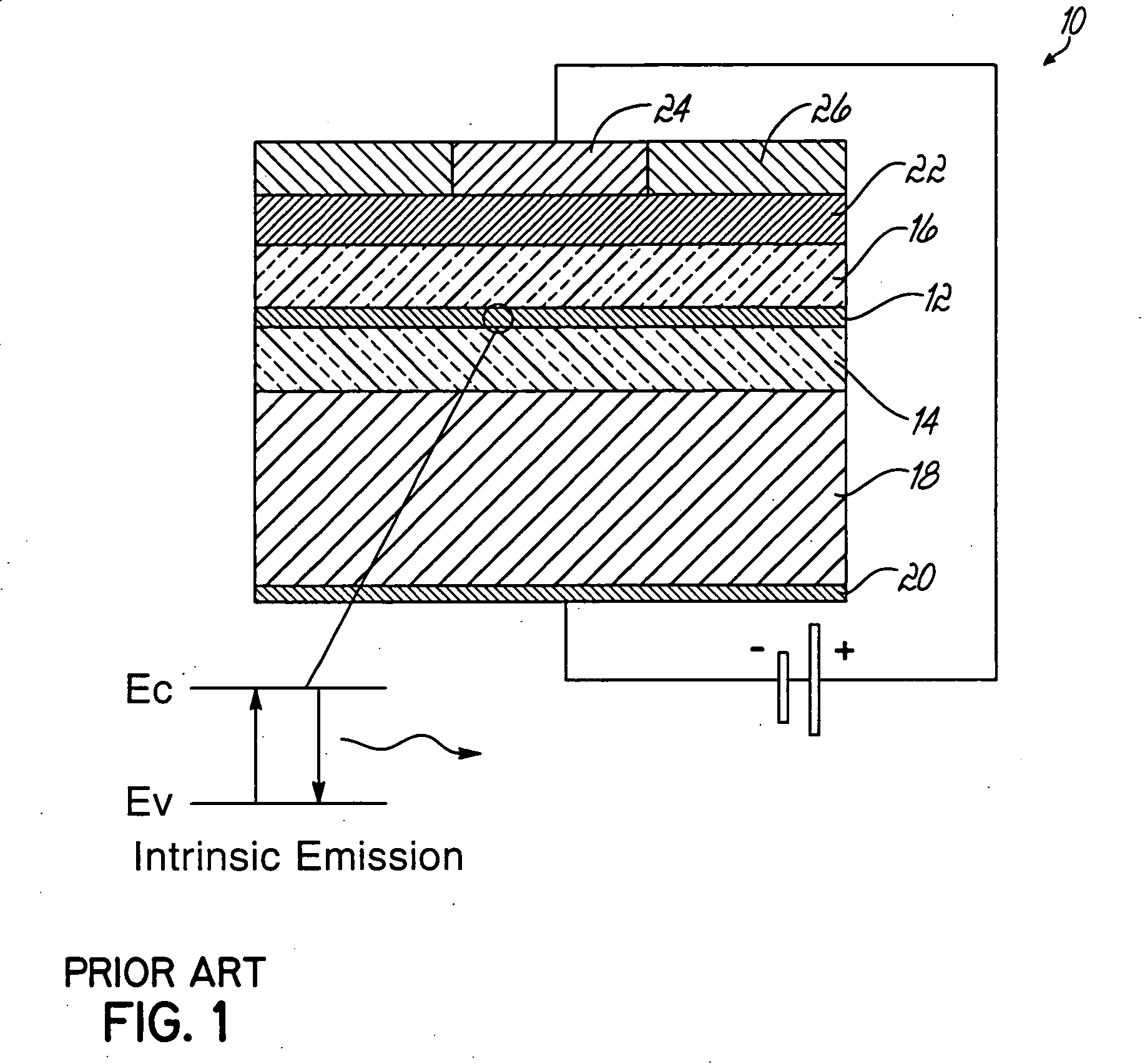
The patent text discusses the limitations of current optical fiber amplifier structures, such as EDFA's and EDWA's, and the need for a more compact and cost-effective alternative. The technical problem addressed is the development of an amplifier structure that does not require an optical pumping source and has an active layer that can be formed without resort to single crystal growth techniques.

Method used


Image

  • Impurity-based electroluminescent waveguide amplifier and methods for amplifying optical data signals
  • Impurity-based electroluminescent waveguide amplifier and methods for amplifying optical data signals
  • Impurity-based electroluminescent waveguide amplifier and methods for amplifying optical data signals

Examples


Embodiment Construction

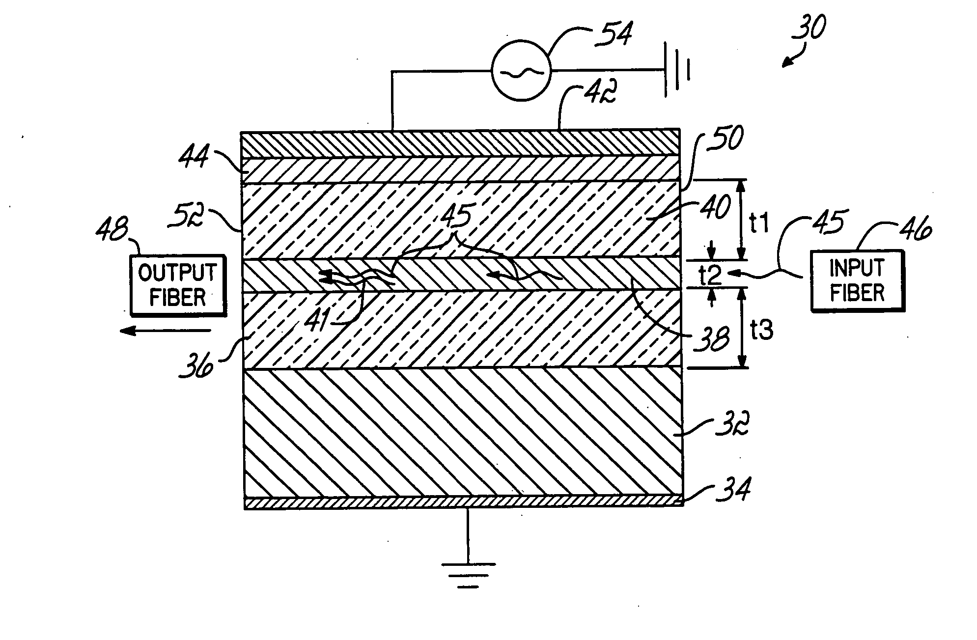
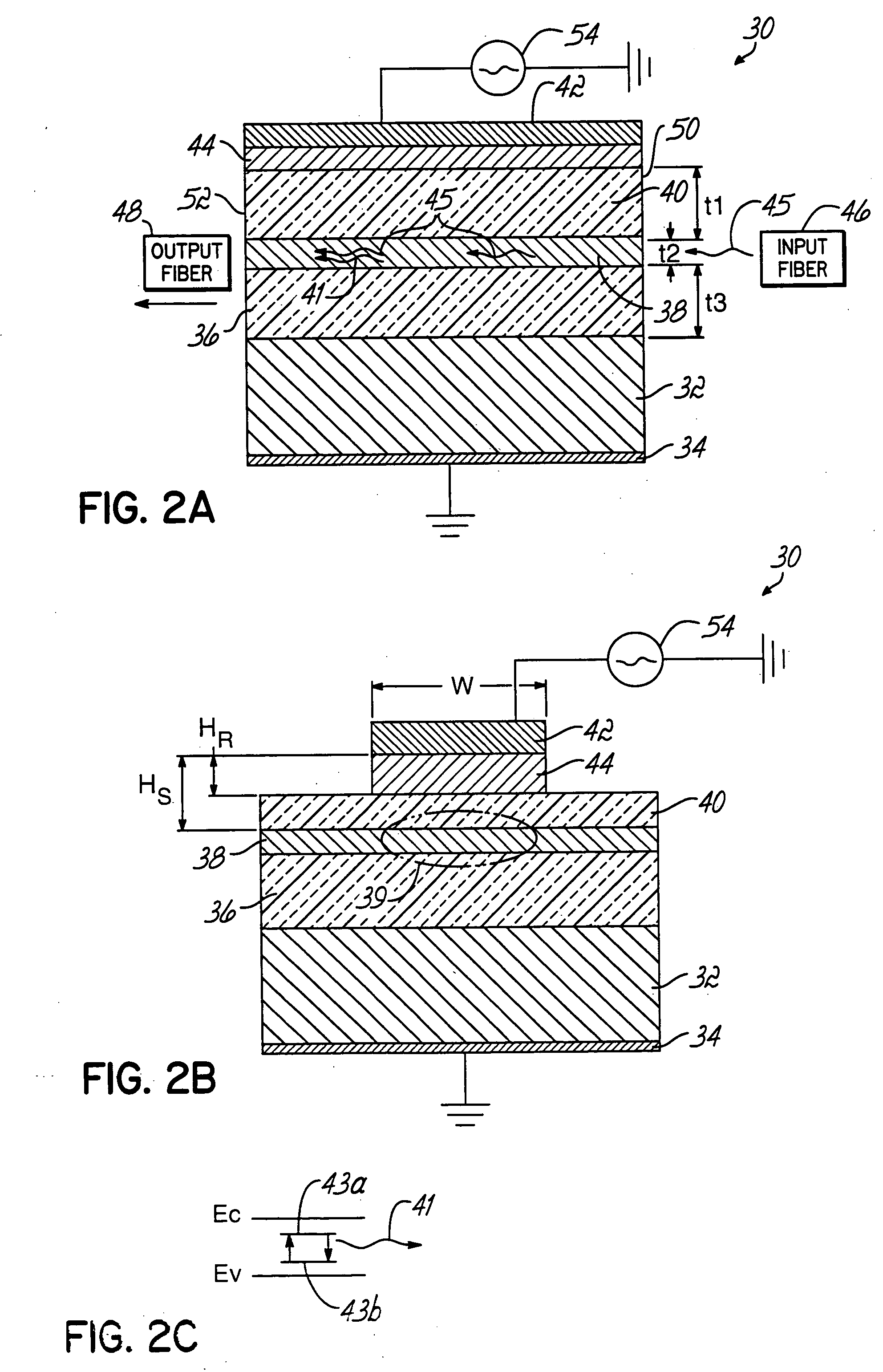
[0024] The present invention is directed to an electroluminescent waveguide amplifier that includes an electroluminescent active layer consisting of a host medium doped with luminescent atoms that amplify propagating signal light or optical data signals through stimulated emission and cladding layers disposed between the active layer and the electrodes, which confine propagating light having the form of optical data signals to the active layer and the cladding layers. The characteristics of the cladding layers also permit coupling of electrical excitation from the device electrodes to the active layer.

[0025] With reference to FIGS. 2A-2B, an electroluminescent waveguide amplifier 30 in accordance with the principles of the invention includes a substrate 32, an electrode 34 applied to one surface of the substrate 32, a lower cladding layer 36 applied to the opposite surface of the substrate 32, an active layer 38 applied on the lower cladding layer 36, an upper cladding layer 40 app...


PUM


Abstract

Electroluminescent waveguide amplifier and methods for amplifying optical data signals in a fiber optical telecommunications system to achieve signal enhancement that compensates for losses incurred by attenuation, optical splitting, and routing through the optical communication system. The waveguide amplifier (30) includes an electroluminescent active layer (38) having a host medium doped with luminescent dopant atoms capable of amplifying a propagating optical data signal (45) by stimulated emission of photons (41). Confining and insulating cladding layers (36, 40) surround the active layer (38) and confine the propagating optical data signals (45) being amplified to the active layer (38) and cladding layers (36, 40).

Description


Claims


Application Information

Patent Timeline
Owner UNIVERSITY OF CINCINNATI
Learn More