Optical unit and image pickup apparatus having the same

an image pickup and optical unit technology, applied in the field of optical units and image pickup apparatuses having the same, can solve the problems of inconvenient minimizing of the body of the apparatus, easy shaking of the camera, and inability to achieve the thinness of the apparatus, so as to achieve the effect of minimizing the size of the apparatus

Active Publication Date: 2006-11-30
KONICA MINOLTA PHOTO IMAGING
View PDF5 Cites 57 Cited by
  • Summary
  • Abstract
  • Description
  • Claims
  • Application Information

AI Technical Summary

Benefits of technology

[0017] An object of the present invention is to provide an optical system having a shaking correction function of high quality image without necessity to have large image...

Problems solved by technology

As a result, camera shaking easily occurs.
However, according to the method of moving a part of the optical system, it is necessary to provide space in which the lens moves and space for placing a mechanism for shifting the lens, which is not suitable for minimizing the body of the apparatus.
Further, there is a problem that making the apparatus thin cannot be achieved because of the space, even when utilizing an inflecting optical system to make the apparatus thin.
Further, according to this method, if the center of the correction lens shifts and coma aberration is generated, there is another problem that focusing performance of the optical system comes down.
Accordingly, there is...

Method used


Image

  • Optical unit and image pickup apparatus having the same
  • Optical unit and image pickup apparatus having the same
  • Optical unit and image pickup apparatus having the same

Examples


first embodiment

THE FIRST EMBODIMENT

[0035] The first embodiment of the present invention will be described below.

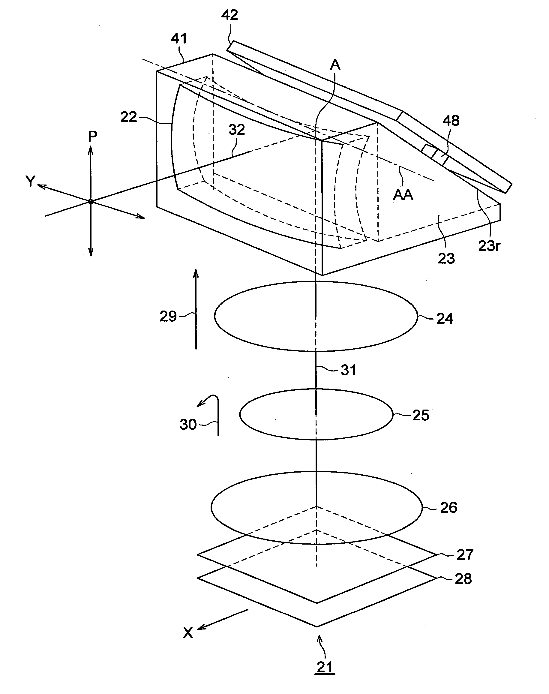
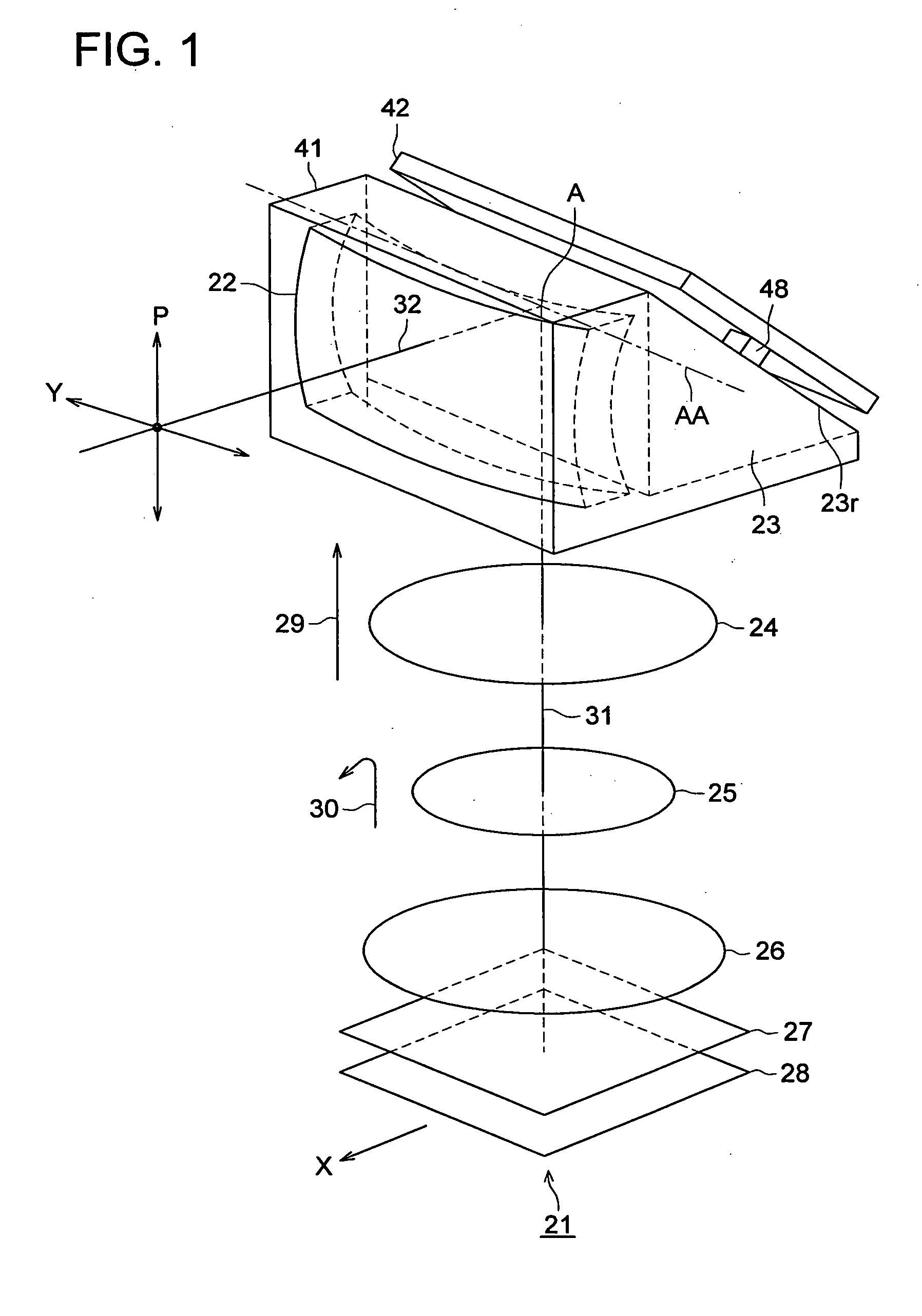
[0036]FIG. 1 illustrates a perspective view of an optical unit 21. In FIG. 1, a symbol 22 denotes the first lens group; a symbol 23 denotes a prism being a reflection member; a symbol 24 denotes the second lens group; a symbol 25 denotes the third lens group; a symbol 26 denotes the fourth lens group; a symbol 27 denotes a low pass filter; and a symbol 28 denotes an image pickup element. The first lens group 22 forms a front lens group positioned in an object side against the reflection member. The second lens group 24, the third lens group 25, the fourth lens group 26 form a rear lens group positioned in an image forming side against the reflection member. A symbol 32 denotes an optical axis of the front lens group and a symbol 31 denotes an optical axis of the rear lens group. The optical axis 32 and the optical axis 31 cross to a reflection surface 23r of the prism 32 at a point A. A...

second embodiment

THE SECOND EMBODIMENT

[0080] The difference between the first and the second embodiment is that the front lens group and the prism in the second embodiment differently move while the first lens group and the prism are driven in one body in the first embodiment. Further, in response to the moving by angle “a” in the P-direction of the prism, the driving angle of the front lens is going to be angle “2 a” in the second embodiment.

[0081] The second embodiment of the present invention will be described below.

[0082]FIG. 9 illustrates a configuration of an optical unit 111 of the embodiment. In FIG. 9, the optical unit 111 employs the same optical design as the first embodiment. The same element having the same functionality as the element shown in FIG. 4 has the same numeral and the explanation will be eliminated. In FIG. 9, a symbol 112 is the case of the first lens group, which includes the first lens group 22. Rack gears 113a and 133b (not shown) are formed on a part of surface of the...

third embodiment

THE THIRD EMBODIMENT

[0096] The third embodiment of the present invention will be described by referring to drawings.

[0097] In the first and second embodiments, a single lens configures the front lens group located in the optical object side of the reflection member. In the third embodiment, a plurality of lens groups configures the front lens groups.

[0098]FIG. 12 illustrates the configuration of an optical unit 131 of the third embodiment. A symbol 132 denotes the first lens group; a symbol 133 denotes the second lens group; a symbol 134 denotes the third lens group; and a symbol 135 denotes a reflection mirror being a reflection member for inflecting the optical axis of the optical axis. A symbol 136 denotes the forth lens group; a symbol 137 denotes the fifth lens group; a symbol 138 denotes a low pass filter; and a symbol 139 denotes an image pickup element. The first lens group—the third lens group configures a front lens group, which is located in the object side in respect t...


PUM


Abstract

An optical unit for forming an object image according to the present invention comprises: a reflection member for banding an optical axis of the optical unit; a front lens group arranged closer to an object side of the optical unit than the reflection member; a rear lens group arranged closer to an image forming side of the optical unit than the reflection member; and a driver for driving the optical unit. The driver drives the reflection member and the front lens group in a predefined first direction and in a predefined second direction.

Description

[0001] The application is based on Japanese Patent Application No. 2005-155150 filed on May 27, 2005, in Japanese Patent Office, the entire content of which is hereby incorporated by reference. FIELD OF THE INVENTION [0002] The present invention relates to an optical unit and an image pickup apparatus having the same. BACKGROUND OF THE INVENTION [0003] In recent years, apparatuses such as digital still cameras, digital movie cameras and cellular phones utilizing a solid state image pickup element have been widely used. With regard to these apparatuses, in order to minimize the size of the apparatus, the demand for increasing the number of pixels of the solid state image pickup elements such as a CCD Sensor and a CMOS sensor, and for minimizing the size of an optical system has been increased. Consequently, as the number of pixels of the solid state image pickup element increase and the optical system is minimized, the size of the pixel in the solid state image pickup element has bee...

Claims


Application Information

Patent Timeline
IPC IPC(8): G02B17/00
CPCG02B27/646G03B2205/0023G03B17/17
Inventor JIN, MAKOTO
Owner KONICA MINOLTA PHOTO IMAGING
Why Eureka
Try Eureka