
Network system and communication method

Inactive Publication Date: 2006-11-30
FUJITSU LTD
View PDF4 Cites 11 Cited by
  • Summary
  • Abstract
  • Description
  • Claims
  • Application Information

AI Technical Summary

Benefits of technology

[0010] Moreover, the present invention is intended to provide the network system and the communication method which enable the P2P application to be executed continuously by preventing the port information (number) newly assigned to the NAT device to be erased.
[0029] Furthermore, according to the present invention, it prevents the port information newly assigned to the NAT device to be erased before another new port information being assigned, allowing the P2P application to be executed continuously.

Problems solved by technology

Since a currently common IP version 4 uses a “32-bits” number for specifying an address, it has become difficult to specify a unique address to each communication terminal as the Internet becomes popularized.
That is, there was a problem that the plurality of communication devices within the same local area have been unable to be connected simultaneously to the Internet.
However, especially with a P2P application, it can not get the private address and the corresponding port number before NAT translation of the communication device on the other side, causing a so-called NAT problem where the P2P application fails.
However, this method is not preferable in that, when a new protocol is developed, it is required to replace the NAT device with a new one compliant with the new protocol, thereby the P2P application may not work correctly until the new NAT device compliant with the new protocol is developed.
Moreover, there is another problem in view of the security because the NAT device updates the packet without permission.

Method used


Image

  • Network system and communication method
  • Network system and communication method
  • Network system and communication method

Examples


first embodiment

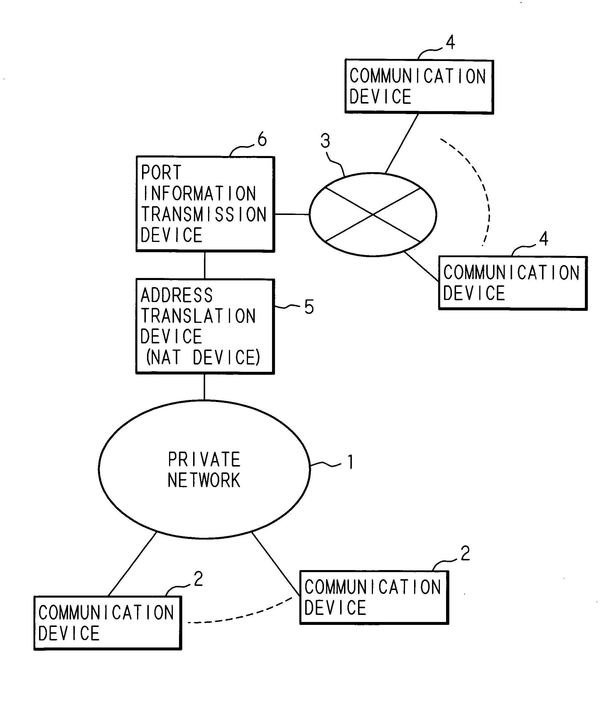
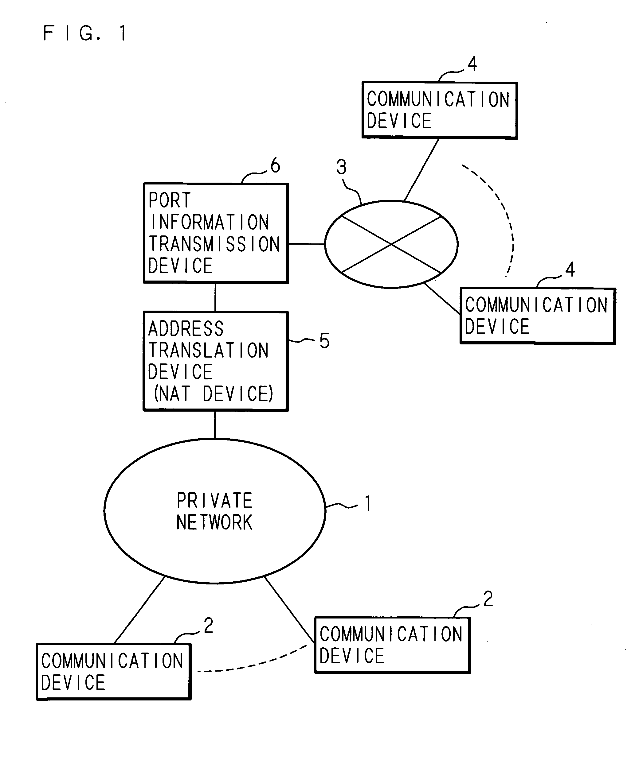
[0049]FIG. 1 is a block diagram illustrating an overall configuration of the network system according to a first embodiment of the present invention. In the first embodiment, the case is assumed where the P2P communication is established between a communication device 2 belonging to a private network 1 where a LAN environment is built and a communication device 4 connected to the private network 1 via a network 3, such as the Internet. Therefore, global addresses are assigned to each of the communication devices 4, 4, . . . , while a single global address is assigned to such as a proxy server within the private network 1.

[0050] Meanwhile, unique private addresses are assigned to each of the communication devices 2, 2, . . . within the private network 1 to enable communication with the external network using the single global address, the private address being translated into the global address by an address translation device (NAT device) 5 to communicate with the communication dev...

second embodiment

[0078] The overall configuration of the network system according to a second embodiment of the present invention is similar to that of the first embodiment. In the second embodiment, it is characterized in that the destination of the pseudo-packet is the arbitrary address. FIG. 8 is a diagram illustrating the relationship between the address and the port number in case that the data is communicated from the communication device 2 within the private network 1 of the network system as the source to the communication device 4 outside the private network 1 as the destination according to the second embodiment of the present invention.

[0079] Here, the address 192.168.1.2 is set as the private address of the communication device 2, while the address 202.153.0.2 is set as the global address of the communication device 4. Usually, the private address and the port number P0 of the communication device 2 are set to be the source address and the address of the communication device 4 to be the...

third embodiment

[0092] The overall configuration of the network system according to a third embodiment of the present invention is similar to that of the first embodiment. In the third embodiment, it is characterized in that the destination of the pseudo-packet is the arbitrary address and the address information (port number information) is added sequentially to the communication packet. FIG. 10 is a diagram illustrating the relationship between the address and the port number in case that data is communicated from the communication device 2 within the private network 1 of the network system as the source to the communication device 4 outside the private network 1 as the destination according to the third embodiment of the present invention.

[0093] Here, the address 192.168.1.2 is set as the private address of the communication device 2, while the address 202.153.0.2 is set as the global address of the communication device 4. Usually, the private address and the port number P0 of the communication...


PUM


Abstract

A network system and a communication method are provided to solve an NAT problem to functionalize a P2P application in case that new port information (number) is assigned to an NAT device. One communication device sends a pseudo-packet containing an address of another communication device, to a port information transmitting device via an address translation device; the port information transmitting device sends a response to the received pseudo-packet to the communication device; and the address translation device assigns new port information corresponding to the communication device address using the response and sends the address of the communication device and the assigned port information to the communication device. The communication device sends the received address of the communication device and the assigned port information to another communication device; and another communication device transmits information with the communication device using the received address of the communication device and the assigned port information.

Description

CROSS-REFERENCE TO RELATED APPLICATIONS [0001] This Nonprovisional application claims priority under 35 U.S.C. §119(a) on Patent Application No. 2005-156149 filed in Japan on May 27, 2005, the entire contents of which are hereby incorporated by reference. BACKGROUND OF THE INVENTION [0002] 1. Field of the Invention [0003] The present invention relates to a network system and a communication method of performing communication via an NAT device using communication devices connected via a network. [0004] 2. Description of the Related Art [0005] Upon communication being performed on the Internet, an Internet protocol (hereinafter, referred to as the IP) is used as a routing protocol. Since a currently common IP version 4 uses a “32-bits” number for specifying an address, it has become difficult to specify a unique address to each communication terminal as the Internet becomes popularized. To solve the problem, a method is developed to use a private address assigned to a predetermined li...

Claims


Application Information

Patent Timeline
IPC IPC(8): H04L12/56H04J3/16H04L12/46H04L12/66H04L12/70
CPCH04L29/12009H04L61/25H04L29/1233H04L61/00
Inventor SONODA, TOSHIHIROIDANI, SHIGEHIRO
Owner FUJITSU LTD
Learn More