Methods and systems for prescribing parameters for tomosynthesis

a technology of tomosynthesis and parameters, applied in the field of prescribing parameters for tomosynthesis, can solve the problems of image that includes motion artifacts, images that include motion artifacts, and the use of standard digital radiography processes and procedures,

Active Publication Date: 2006-11-30
GENERAL ELECTRIC CO
View PDF1 Cites 55 Cited by
  • Summary
  • Abstract
  • Description
  • Claims
  • Application Information

AI Technical Summary

Benefits of technology

[0021] The foregoing summary, as well as the following detailed description of certain embodiments of the present application, will be better understood when read in conjunction with the appended drawings. For the purpose of illustrating the invention, certain embodiments are shown in the drawings. It should be u...

Problems solved by technology

As a result, the use of standard digital radiography processes and procedures presents a number of potential problems when used in the performance of digital tomosynthesis.
For example, patient motion in-between the successive acquisitions may result in images that include motion artifacts.
Similarly, physiologic motion (e.g., motion of the heart, lungs, etc.) in-between the successive acquisitions may also result in images that include motion artifacts.
Other potential problems, such as intensity and resolution non-uniformities, may arise as a result of the angulation of the source of the x-rays relative to the detector.
Yet ...

Method used


Image

  • Methods and systems for prescribing parameters for tomosynthesis
  • Methods and systems for prescribing parameters for tomosynthesis
  • Methods and systems for prescribing parameters for tomosynthesis

Examples


Embodiment Construction

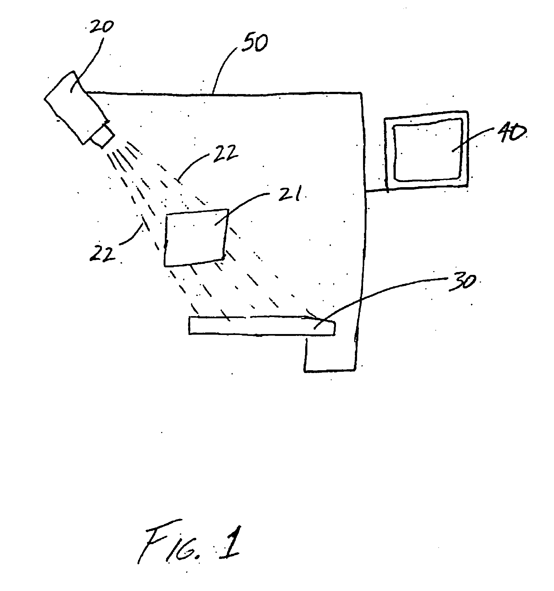
[0022] Referring to FIG. 1, a tomosynthesis system 10 is shown schematically according to a preferred embodiment. Tomosynthesis system 10 includes an x-ray source 20, a detector 30, a computer 40, and supporting structure 50.

[0023] X-ray source 20 is directed toward a subject 21 (e.g., object, patient, etc.) and is configured to emit a beam of x-rays 22 at desired times. Once x-rays 22 are emitted, they pass through subject 21 and are picked up by, or hit, detector 30.

[0024] Detector 30 (e.g., x-ray detector, digital radiography detector, flat panel detector, flat detector, etc.) may be any one of a variety of different detectors conventionally known within the art or that will become available in the future (e.g., energy discriminating detectors that are theoretically capable of acquiring high and low energy images simultaneously). However, according to a preferred embodiment, detector 30 is a flat panel digital detector. When x-rays 22 are picked up by detector 30, they are conv...


PUM


Abstract

Certain embodiments of the present invention provide a method for performing tomosynthesis including: receiving an image representative of an anatomy of a patient; allowing an interaction with the image to arrange at least one element with respect to the image to form an arrangement; and prescribing at least one parameter for obtaining a tomosynthesis image based at least in part on the arrangement. In an embodiment, the method further includes performing tomosynthesis in accordance with the at least one parameter. In an embodiment, the at least one element includes a detector representation. In an embodiment, the at least one element includes at least one thickness guide. In an embodiment, the at least one element includes at least one slice location guide. In an embodiment, the at least one parameter includes at least one of: a detector position, a detector size, a thickness size, a thickness position, a slice size, a slice position, a slice thickness, a slice separation, a field of view, a reconstruction algorithm, a hanging protocol, and an image processing routine. In an embodiment, the at least one parameter includes at least one of: an x-ray source location, an x-ray source angulation, an x-ray beam intensity, an x-ray beam gating, and a detector sensitivity.

Description

[0001] This application is a continuation-in-part of U.S. patent application Ser. No. 10 / 613,591, filed on Jul. 3, 2003, which is herein incorporated by reference in its entirety.FEDERALLY SPONSORED RESEARCH OR DEVELOPMENT [0002] [Not Applicable]MICROFICHE / COPYRIGHT REFERENCE [0003] [Not Applicable]BACKGROUND OF THE INVENTION [0004] Embodiments of the present application relate generally to prescribing parameters for tomosynthesis. Particularly, certain embodiments relate to prescribing parameters based on an interaction with a localization image. [0005] Digital tomosynthesis imaging is a technique that requires the acquisition of multiple x-ray images at different angles relative to the patient within a relatively short time interval. Once these images have been acquired, a reconstruction algorithm is applied to the data represented by the images to reconstruct “slices” through the patient. These slices, which are essentially re-constructed x-ray images of selected planes within an...

Claims


Application Information

Patent Timeline
IPC IPC(8): G06K9/00G06T5/00G06T11/00
CPCG06T11/005G06T11/008G06T5/00G06T2207/30004G06T2211/436G06T2207/10112G06V2201/03
Inventor METZ, STEPHEN WAYNE
Owner GENERAL ELECTRIC CO
Why Eureka
Try Eureka