Lithographic apparatus and device manufacturing method utilizing 2D run length encoding for image data compression

a technology of image data compression and lithographic apparatus, which is applied in the direction of photomechanical apparatus, instruments, optics, etc., can solve the problem of becoming difficult for complex device patterns

Active Publication Date: 2006-11-30
ASML NETHERLANDS BV
View PDF23 Cites 47 Cited by
  • Summary
  • Abstract
  • Description
  • Claims
  • Application Information

AI Technical Summary

Benefits of technology

[0010] In one embodiment, there is provided a lithographic apparatus comprising an array of individually controllable elements and a data processing pipeline. The array of individually controllable elements modulates a beam of radiation. The data processing pipeline converts a first representation of a requested dose pattern to a sequence of control data suitable for controlling the array of individually controllable elements in order substantially to form the requested dose pattern on a substrate. The data processing pipeline comprises an offline pre-processing device and an online rasterizer. The offline pre-processing device converts the first representation of the requested dose pattern to an intermediate representation, which can be rasterized in a fewer number of operations than the first representation. The storage device stores the intermediate representation. The online rasterizer accesses the stored intermediate representation and produces therefrom a stream of bitmap data to be used to generate the sequence of control data substantially in real time.

Problems solved by technology

This becomes difficult for complex device patterns due to the enormous size of the bitmap representations and the associated difficulties concerning storage, data conversion steps (to the bitmap data, for example) and / or transmission, for example.

Method used


Image

  • Lithographic apparatus and device manufacturing method utilizing 2D run length encoding for image data compression
  • Lithographic apparatus and device manufacturing method utilizing 2D run length encoding for image data compression
  • Lithographic apparatus and device manufacturing method utilizing 2D run length encoding for image data compression

Examples


Embodiment Construction

[0029] While specific configurations and arrangements are discussed, it should be understood that this is done for illustrative purposes only. A person skilled in the pertinent art will recognize that other configurations and arrangements can be used without departing from the spirit and scope of the present invention. It will be apparent to a person skilled in the pertinent art that this invention can also be employed in a variety of other applications.

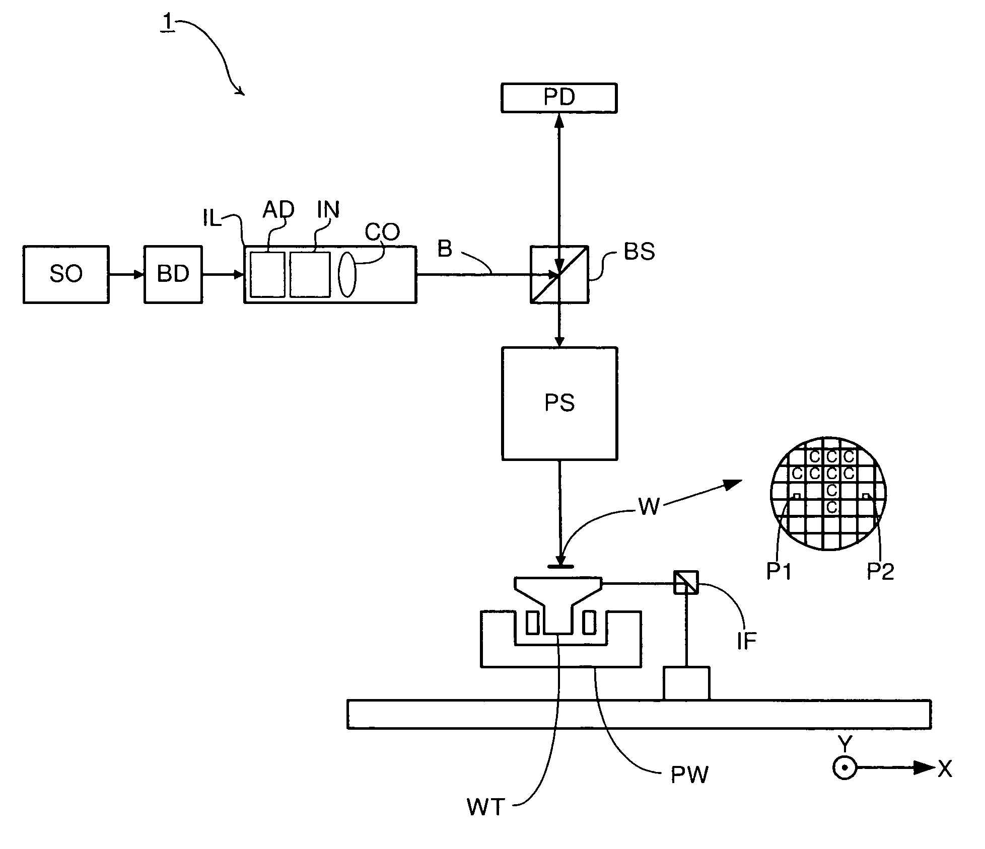
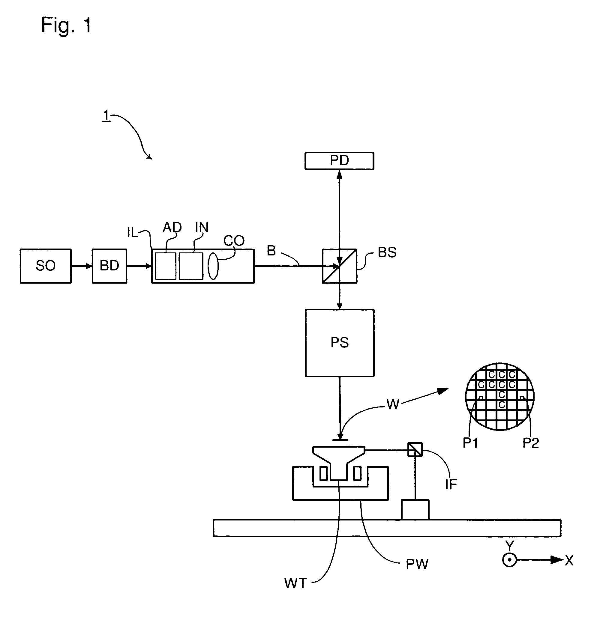
[0030]FIG. 1 schematically depicts a lithographic apparatus according to one embodiment of the invention. The apparatus comprises an illumination system EL, a patterning device PD, a substrate table WT, and a projection system PS. The illumination system (illuminator) IL is configured to condition a radiation beam B (e.g., UV radiation).

[0031] The patterning device PD (e.g., a reticle or mask or an array of individually controllable elements) modulates the projection beam. In general, the position of the array of individually contr...


PUM


Abstract

A lithographic apparatus comprises an array of individually controllable elements and a data processing pipeline. The array of individually controllable elements modulates a beam of radiation. The data processing pipeline converts a first representation of a requested dose pattern to a sequence of control data suitable for controlling the array of individually controllable elements in order substantially to form the requested dose pattern on a substrate. The data processing pipeline comprises an offline pre-processing device and an online rasterizer. The offline pre-processing device converts the first representation of the requested dose pattern to an intermediate representation, which can be rasterized in a fewer number of operations than the first representation. The storage device stores the intermediate representation. The online rasterizer accesses the stored intermediate representation and produces therefrom a stream of bitmap data to be used to generate the sequence of control data substantially in real time.

Description

BACKGROUND [0001] 1. Field [0002] The present invention relates to a lithographic apparatus and a method for manufacturing a device. [0003] 2. Related Art [0004] A lithographic apparatus is a machine that applies a desired pattern onto a substrate or part of a substrate. A lithographic apparatus can be used, for example, in the manufacture of flat panel displays, integrated circuits (ICs) and other devices involving fine structures. In a conventional apparatus, a patterning device, which can be referred to as a mask or a reticle, can be used to generate a circuit pattern corresponding to an individual layer of a flat panel display (or other device). This pattern can be transferred on (part of) the substrate (e.g., a glass plate), e.g., via imaging onto a layer of radiation-sensitive material (resist) provided on the substrate. [0005] Instead of a circuit pattern, the patterning means can be used to generate other patterns, for example a color filter pattern or a matrix of dots. Inst...

Claims


Application Information

Patent Timeline
Patent Type & Authority Applications(United States)
IPC IPC(8): G06K9/00
CPCG03F7/70291G03F7/70558G03F7/70508
Inventor MAKAROVIC, ANDREJVENEMA, WILLEM JURRIANUSKESSELS, LAMBERTUS GERARDUS MARIABONTEKOE, MARCEL
Owner ASML NETHERLANDS BV
Why Eureka
Try Eureka