
Optical transceiver with function for monitoring operating and ambient conditions

a transceiver and operating condition technology, applied in the field of optical transceivers, can solve the problems of trouble not being investigated, broken or extremely shortening the life of the optical transceiver, and unclear how far the optical transceiver is from the threshold, so as to facilitate the investigation

Inactive Publication Date: 2006-11-30
SUMITOMO ELECTRIC IND LTD
View PDF5 Cites 26 Cited by
  • Summary
  • Abstract
  • Description
  • Claims
  • Application Information

AI Technical Summary

Benefits of technology

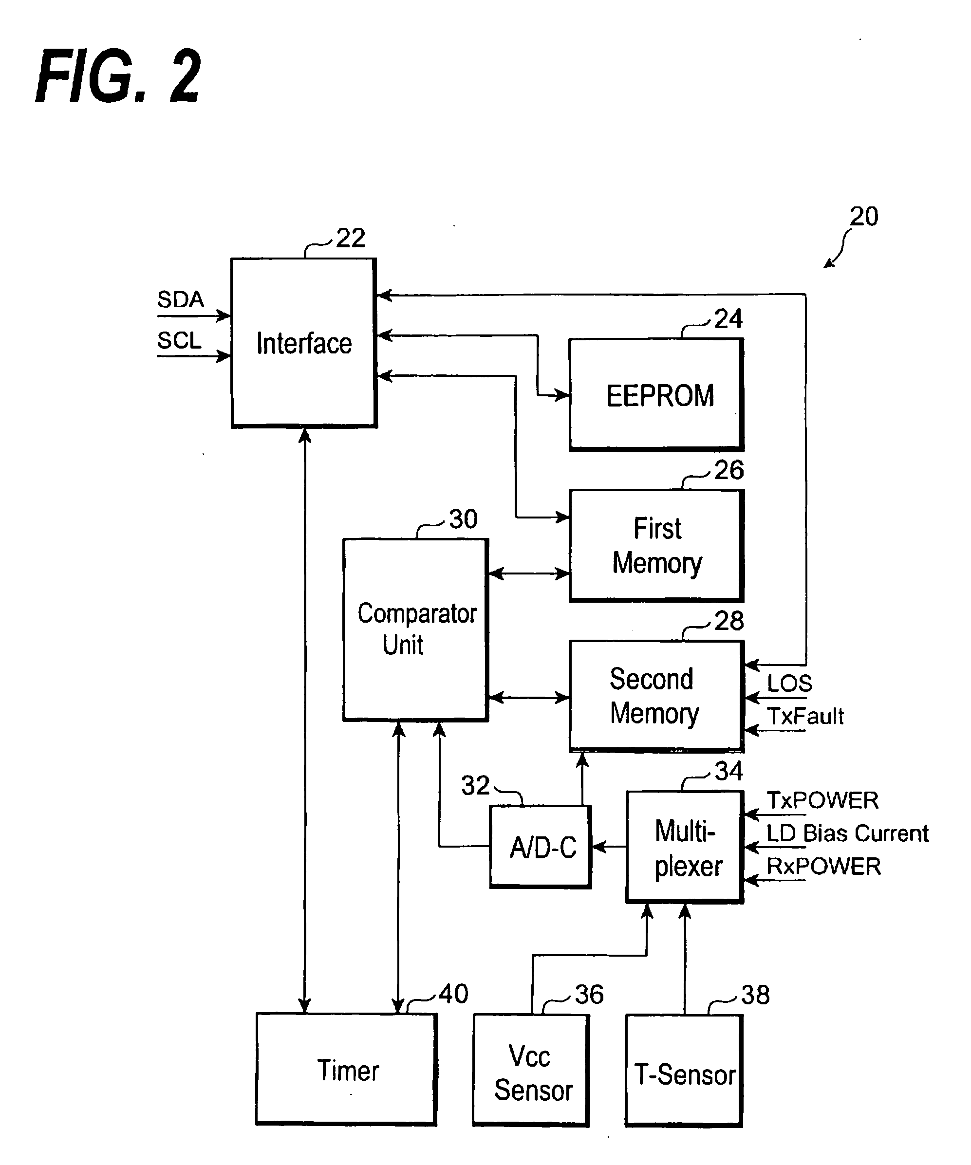
[0008] The optical transceiver may further provide a timer to count an operating time of the transceiver and to store an accumulated time. The comparator unit may store the accumulated time in connection with the rewriting of the maximum or minimum value in the first memory. This may further facilitate the investigation of the cause of the trouble occurred in the transceiver.

Problems solved by technology

An optical transceiver causes a breakdown or extremely shortens its life when it is used in conditions out of the guaranteed range, for example, a power supply out of the guaranteed voltage or a temperature out of the operable range.
However, in the case that only the error flag is set in the memory, it left unclear how apart the monitored value from the threshold.
Accordingly, even if the monitored value exceeds the threshold, the cause of the trouble may be not investigated.

Method used


Image

  • Optical transceiver with function for monitoring operating and ambient conditions
  • Optical transceiver with function for monitoring operating and ambient conditions
  • Optical transceiver with function for monitoring operating and ambient conditions

Examples


Embodiment Construction

[0011] Next, preferred embodiments of the present invention will be described as referring to accompanying drawings. In the specification and the drawings, the same symbols or numerals will refer to the same elements without overlapping explanations.

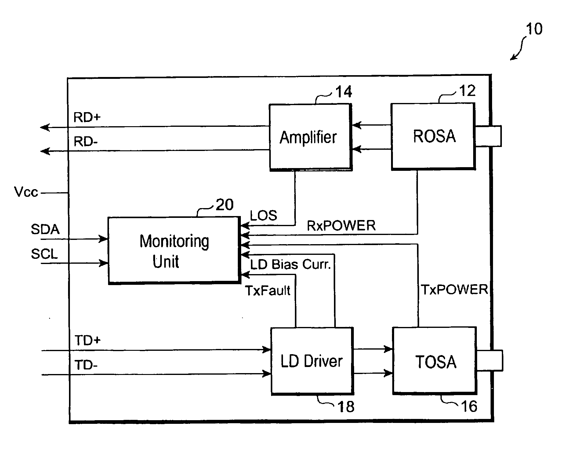
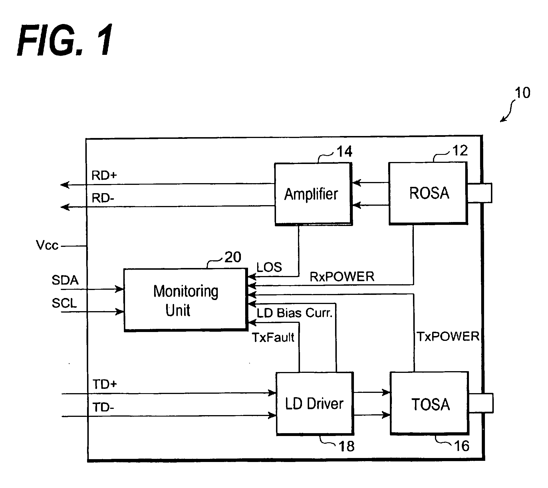
[0012]FIG. 1 is a schematic block diagram of an optical transceiver according to an embodiment of the present invention. The optical transceiver 10, which has a function of the optical transmitter and the optical receiver, comprises a receiving optical sub-assembly (hereinafter denoted as ROSA) 12, an amplifier 14, a transmitting optical sub-assembly (hereinafter denoted as TOSA) 16, a laser driver 18, and a monitoring unit 20.

[0013] The ROSA 12 is configured to receive an optical input to the optical transceiver 10, and to generate an electrical output corresponding to the optical input. The ROSA 12 includes a photodiode (hereinafter denoted as PD) to receive the optical input and to convert it into the electrical output. The amplifie...


PUM


Abstract

The present invention is to provide an optical transceiver with a function to investigate a cause of a trouble in facilitated. The transceiver of the invention includes various monitoring unit that monitors parameters of operating and ambient conditions, a first memory that stores at least one of the maximum and the minimum of each monitored parameter, and a comparator unit that compares the monitored parameter with at least one of the maximum and minimum value stored in the first memory and rewrites the first memory. This comparator unit rewrites the first memory when the monitored parameter is greater than the maximum value in the memory or the monitored parameter is smaller than the minimum value in the memory.

Description

BACKGROUND OF THE INVENTION [0001] 1. Field of the Invention [0002] The present invention relates to an optical transceiver with functions of the optical transmission and the optical reception. [0003] 2. Related Art [0004] An optical transceiver causes a breakdown or extremely shortens its life when it is used in conditions out of the guaranteed range, for example, a power supply out of the guaranteed voltage or a temperature out of the operable range. The United States patent application published as US 2002 / 0149821A has disclosed an optical transceiver with a monitoring function to investigate the trouble or the extraordinary operating condition promptly. In the optical transceiver disclosed therein sets an error flag in a memory when a monitored parameter is out of a threshold range. [0005] However, in the case that only the error flag is set in the memory, it left unclear how apart the monitored value from the threshold. Accordingly, even if the monitored value exceeds the thres...

Claims


Application Information

Patent Timeline
Patent Type & Authority Applications(United States)
IPC IPC(8): H04B10/08H04B10/07H04B10/079H04B10/40H04B10/50H04B10/60H04B17/00
CPCH04B10/40H04B10/0799
Inventor IWADATE, HIROTAKE
Owner SUMITOMO ELECTRIC IND LTD
Learn More