Crossllink for securing spinal rods

a technology of connecting member and spinal rod, which is applied in the field of connecting member, can solve the problems of increasing the number of obstacles encountered affecting the healing process, etc., and achieves the effect of avoiding torque-limiting devices, quick and easy connection, and minimizing the outer dimension of the sleev

Inactive Publication Date: 2006-11-30
PIONEER SURGICAL TECH INC
View PDF52 Cites 88 Cited by
  • Summary
  • Abstract
  • Description
  • Claims
  • Application Information

AI Technical Summary

Benefits of technology

[0012] In accordance with one aspect of the present invention, an improved crosslink connecting member for securing spinal rods to each other is disclosed. The crosslink has opposed connecting ends for securing the crosslink to the upper portion of a pair of spinal rods which are, in turn, secured to a patient's vertebrae, such as by pedicle screws. Each connector end has a central longitudinal axis and a curved end, in the form of a bracket or brace, which extends along the upper portion of the spinal rod, and partially around the lateral sides of the spinal rods. The curved end forms an arcuate inner surface for resting on and securing with the outer surface of the spinal rod. The arcuate inner surface extends orthogonally to the central longitudinal axis of the connector end or, alternatively, slightly back towards the opposing connector end. The curved end also forms an arcuate outer surface which curves around a portion of the spinal rod. The size and extension of the arcuate outer surface of the curved end is preferably shaped so that the wall thickness of the curved end is optimized to provide sufficient strength to the curved end while minimizing its size. Such a configuration minimizes the clearance required laterally, above, and below the spinal rods for seating the crosslink on the spinal rods.

Problems solved by technology

When utilizing crosslinking or connecting members to secure pedicle screws, a number of obstacles are commonly encountered.
Often, the patient's soft tissue must be cleared for this purpose, a result which may exacerbate pain, discomfort, and healing time.
When a set screw drives against a spinal rod or other fixture, damage and distortion may occur at the interface.
This can lead to uneven securement by the set screw, localized weakening of the fixture, loosening of the screw, or debris ground from either the screw or the fixture.
Additionally, the screws require a threaded path long enough to provide a secure hold for the screw, which adds to the material cost, to the size of the fixture, and to the invasiveness of the procedure.
Moreover, the use of a set screw in the central fastening area presents a danger to the patient.

Method used


Image

  • Crossllink for securing spinal rods
  • Crossllink for securing spinal rods
  • Crossllink for securing spinal rods

Examples


Embodiment Construction

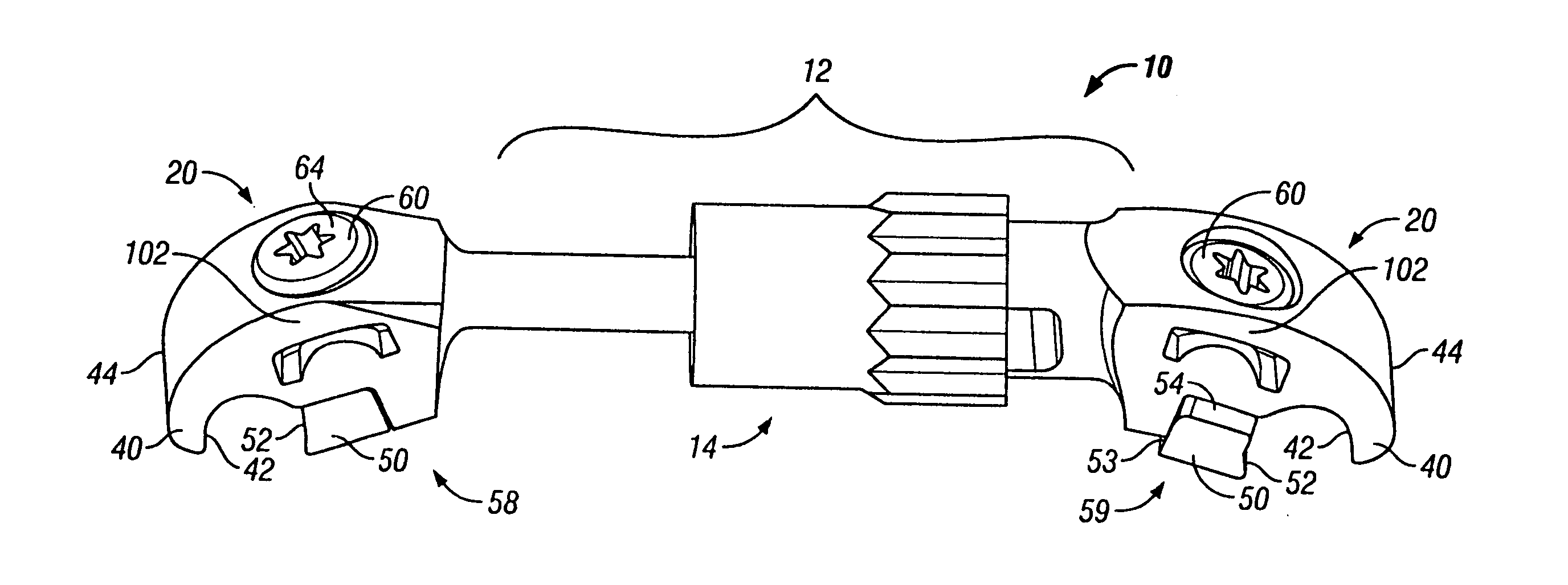
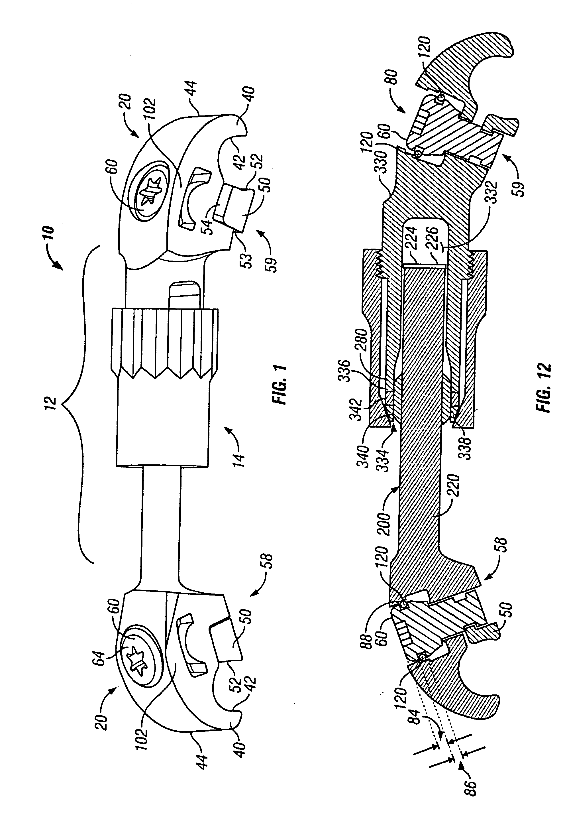
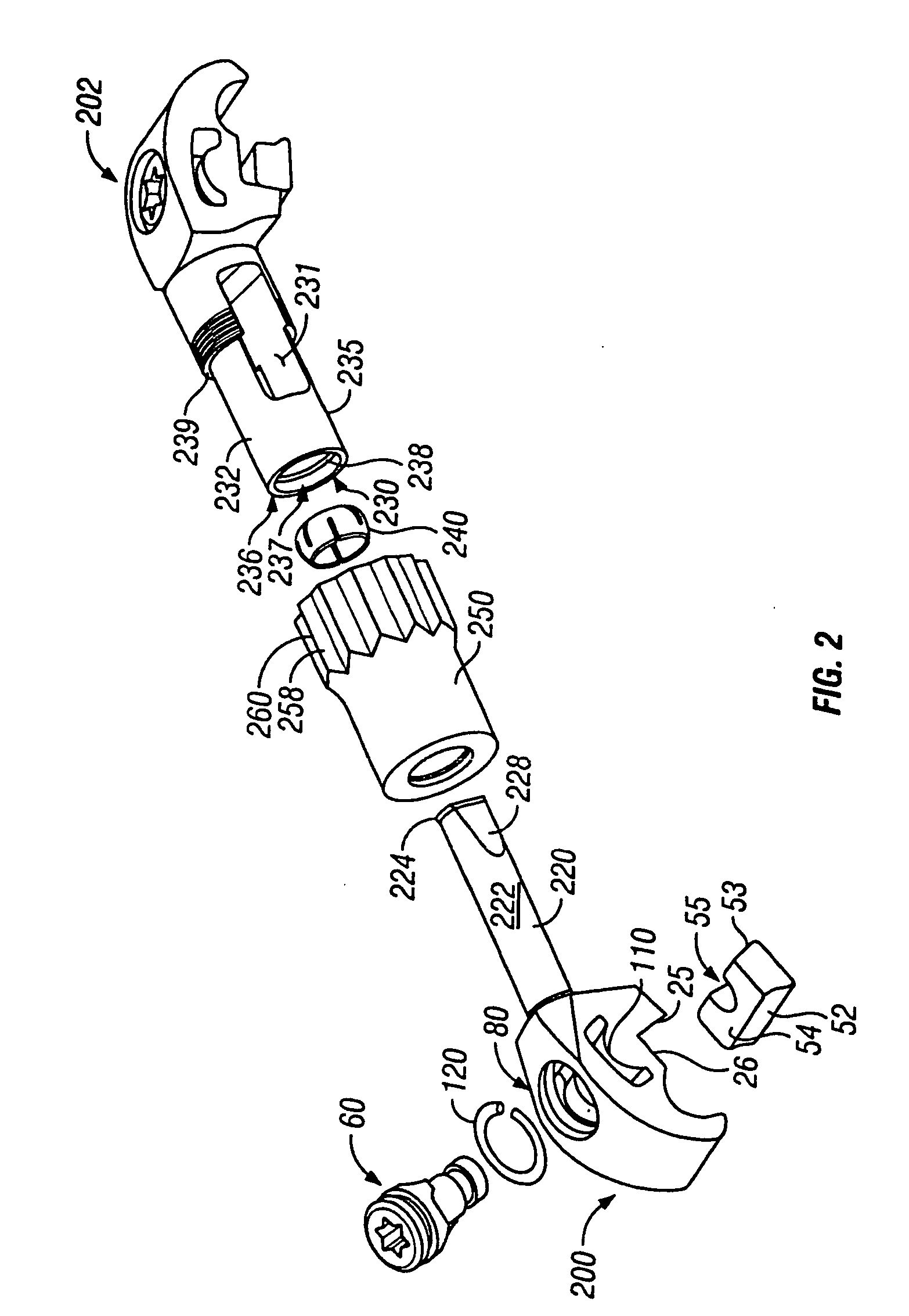
[0039] Referring initially to FIGS. 1-3, a crosslink or connecting member 10 is depicted having two connecting ends or connectors 20 and a central span 12. In some embodiments, the central span 12 may simply be a rod or bar-like structure secured to or integral with the connectors 20. In other embodiments, the span may be a central connection portion 14 formed by the two connectors 20 with an ability to be adjusted, as will be discussed in greater detail below. In such a case, one connector 20 may be provided as a male connector or cross rod connector 200, and the other connector 20 may be provided as a rod receiving female connector 202, as will be discussed below. The preferred crosslink 10 may have an overall length, for instance, of 11 mm, 30 mm, 80 mm, or any length therebetween, and may have telescoping lengths covering the same range. However, many other lengths are possible including lengths outside this range.

[0040] The crosslink 10 spans between a pair of spinal rods 30 (...


PUM


Abstract

A crosslink member for securing spinal rods is disclosed having connector ends that include a brace and a locking member, each having an arcuate face resting on and securing a spinal rod. The locking member is secured by a cam member that rotates relative to the locking member and that cams against the connector to displace the cam member. The crosslink includes a male connector with a cylindrical cross rod received by a cavity in a female connector. The cross rod is secured by a pivotable clamp device in the female connector, and the cross rod connector and female connector may pivot, rotate, and telescope relative to each other. To reduce size without sacrificing pivot sweep, the cross rod has beveled edges, and the cavity of the female connector has windows to provide pivot clearance.

Description

CROSS-REFERENCE TO RELATED APPLICATIONS [0001] This application is a continuation of International application No. PCT / US2004 / 034897, filed Oct. 21, 2004, which is a continuation of U.S. patent application Ser. No. 10 / 692,460, filed Oct. 22, 2003, the contents of which are fully incorporated herein by reference.FIELD OF THE INVENTION [0002] The invention relates to a crosslink or connecting member to secure multiple spinal rods in relation to each other and, in particular, to a connecting member with a cam-locking mechanism for securing on multiple spinal rods. BACKGROUND OF THE INVENTION [0003] In surgical procedures involving the spine, it is common to secure a pair of spinal rods to a series of vertebrae. Furthermore, it is often necessary or desirable to secure the spinal rods relative to each other. [0004] A spinal rod is often secured to the pedicle portion of a vertebrae by a screw. Surgical procedures involving the spine benefit from minimal invasiveness of the surgery from ...

Claims


Application Information

Patent Timeline
Patent Type & Authority Applications(United States)
IPC IPC(8): A61F2/30A61B17/70
CPCA61B17/7052
Inventor BERREVOETS, GREGORYJANOWSKI, BRIAN P.KILPELA, THOMAS S.
Owner PIONEER SURGICAL TECH INC
Why Eureka
Try Eureka