Trap for rodents, in particular for mice and rats

a rodent and rodent technology, applied in the field of rodent traps, can solve the problems of limited efficiency of traps and inability to stack traps, and achieve the effects of reducing space requirements and shipping costs, efficient killing small rodents, and high striking for

Inactive Publication Date: 2006-12-07
URBANGUARD
View PDF0 Cites 31 Cited by
  • Summary
  • Abstract
  • Description
  • Claims
  • Application Information

AI Technical Summary

Benefits of technology

[0005] The invention is based on the objective of developing a trap of the initially described type that is intended, in particular, for use in private households and agricultural farming, especially in poultry farming, and makes it possible to efficiently kill small rodents, particularly mice and rats, in a humane fashion with a high a striking force, wherein even inexperienced persons should be able to comfortably operate the trap with one hand. In addition, the trap should be designed in a stackable fashion in order to red

Problems solved by technology

The efficiency of this trap is limited because it cannot be ensured that an animal to be trapped raises the hood-li

Method used


Image

  • Trap for rodents, in particular for mice and rats
  • Trap for rodents, in particular for mice and rats
  • Trap for rodents, in particular for mice and rats

Examples


Embodiment Construction

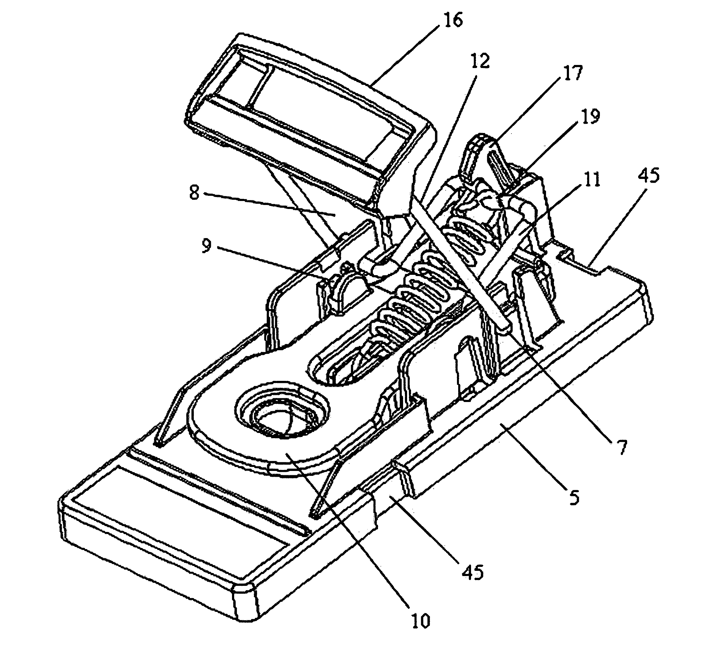
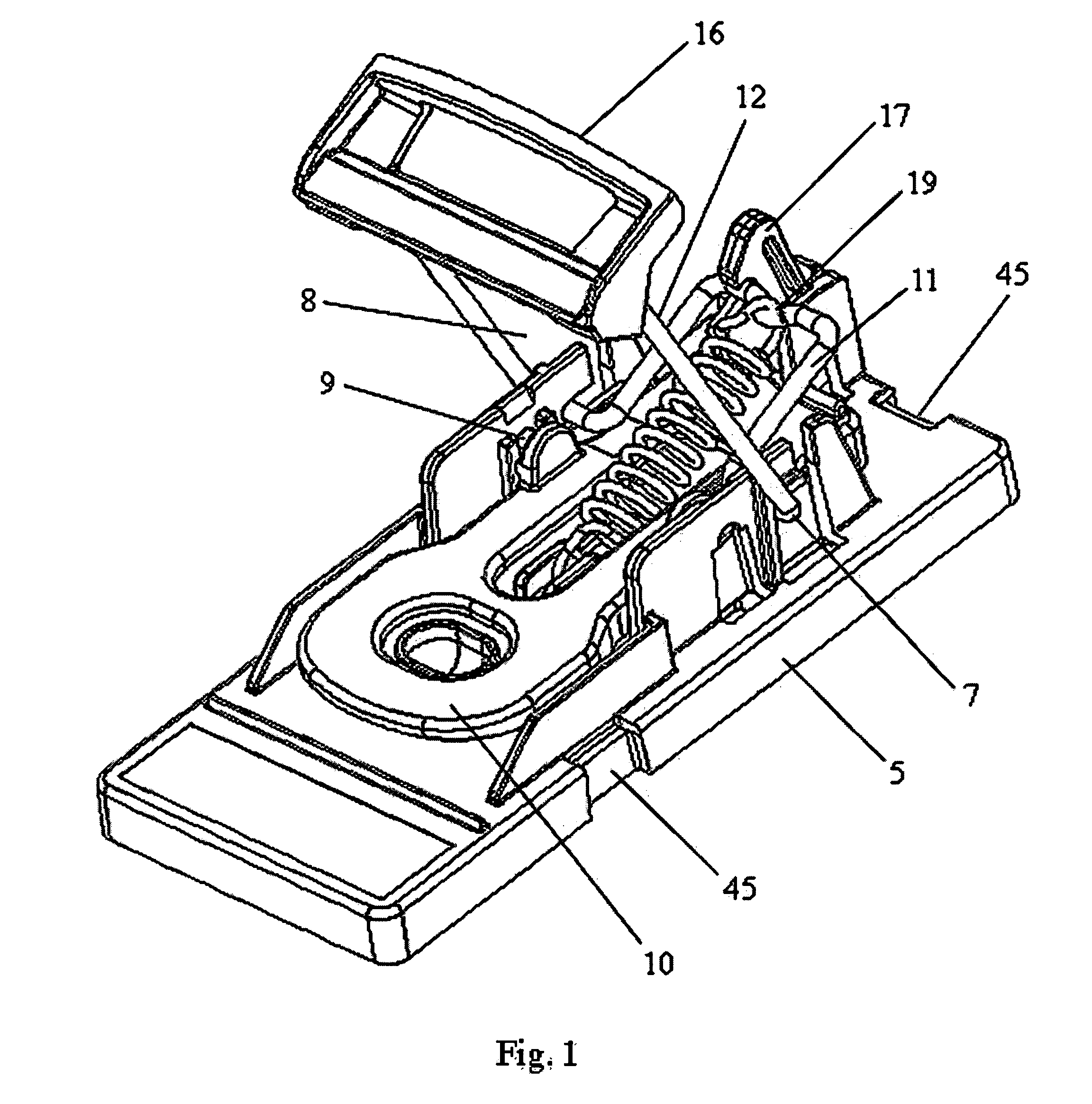
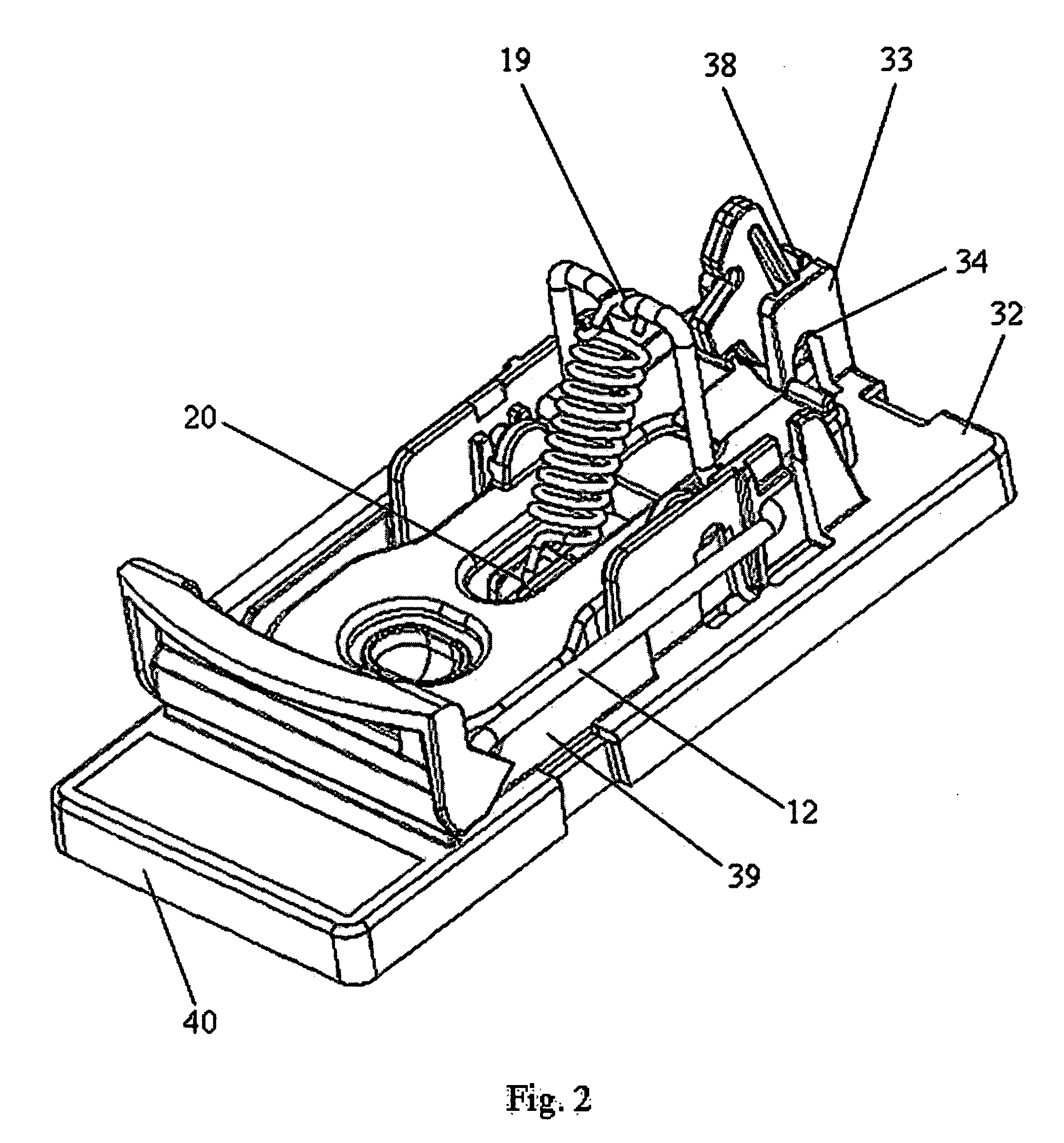
[0039] According to FIGS. 1, 2, 6 and 7 that show the embodiment of the trap from different viewing directions, the trap comprises a base plate 1 that is illustrated separately in FIGS. 3 and 4. In the region of its front section, the base plate 1 is provided with a bait receptacle 4 that lies on its longitudinal axis 2 and extends upward from the upper surface 3 of the base plate 1. Wall-like holding elements 6 extend parallel to the longitudinal edges 5 of the base plate 1 from approximately the longitudinal center of the base plate into the rear section of the base plate 1 on both sides, wherein the first axis 7, i.e., the pivoting axis of the striking device 8 of the trap, as well as the second axis 9, i.e., the pivoting axis of the trigger device 10 of the trap, are guided transverse to the longitudinal axis 2 of the base plate 1 in said holding elements. FIG. 8 shows most clearly that the striking device 8 is realized in the form of a bracket with a first arm 11 and two identi...


PUM


Abstract

The invention pertains to a trap for rodents, particularly for mice and rats, with a trigger device in the form of a plate (10) that is supported in a rocker-like fashion and provided with a constantly accessible receptacle for accommodating bait, with a striking device that is supported on the base plate (1) such that it can be pivoted about a first axis (7), wherein the striking device can be subjected to the force of a tension spring (18) and released from a first, armed position when an animal acts upon the plate such that it is pivoted about a second axis (9) supported on the base plate (1) from an idle position into a triggering position, in which a release element in the form of an eccentrically supported, elastic driving element that is separably engaged with the striking device (8) in the first, armed position can be pivoted by the rocker-like plate (10), wherein the striking device (8) that can be pivoted about the first axis (7) is released from its first, armed position and the force of the tension spring (18) causes the striking device to instantly swing with a high striking force into a second position, in which it humanely kills the animal. Due to its rotative moment, the eccentrically supported elastic driving element (17) is always rotationally prestressed in the direction of its home position, in which a collar (35) of the driving element (17) is engaged with an abutment (27) of the plate (10), wherein the striking device (8) is separably locked in its first, armed position on the driving element (17). The collar (35) of the driving element (17) that is tensioned during the movement of the latter into the release position such that the driving element (17) is turned back in the direction of its home position due to the spring-back of the spring arm (36).

Description

SUBJECT AREA AND BACKGROUND OF THE INVENTION [0001] The invention pertains to a trap for small rodents, particularly for mice and rats, with a base plate that is provided with a receptacle for accommodating bait, with a striking device that is supported on the base plate such that it can be pivoted about a first axis, wherein the striking device can be subjected to the force of a tension spring and released from a first, armed position when an animal acts upon a trigger device such that it is pivoted about a second axis supported on the base plate from an idle position into a triggering position, in which a release element that is engaged with the striking device in the first, armed position can be pivoted by the trigger device in such a way that the striking device that can be pivoted about the first axis is released from its first, armed position and the force of the tension spring causes the striking device to instantly swing into a second position, in which it strikes and kills ...

Claims


Application Information

Patent Timeline
IPC IPC(8): A01M23/30
CPCA01M23/30A01M23/245
Inventor WIESENER, BERNDWIESENER, MARK
Owner URBANGUARD
Why Eureka
Try Eureka