Method of calibrating zero offset of a pressure sensor

Inactive Publication Date: 2006-12-07
TOUCH MICRO SYST TECH
View PDF8 Cites 15 Cited by
  • Summary
  • Abstract
  • Description
  • Claims
  • Application Information

AI Technical Summary

Benefits of technology

[0014] The method of calibrating the zero offset of the pressure sensors in the claimed invention is to measure the zero offset of the pressure sensor test sample first, and then, according to the zero offset, to form a stress-adjusting thin film on the surface of a diaphr

Problems solved by technology

As soon as the zero offset increases excessively, the difficulty of circuit design increases, the performance of the piezoresistive pressure sensor 10 decreases, and the cost of calibration increases.
Although laser trimming can change the resistance of the

Method used


Image

  • Method of calibrating zero offset of a pressure sensor
  • Method of calibrating zero offset of a pressure sensor
  • Method of calibrating zero offset of a pressure sensor

Examples


Embodiment Construction

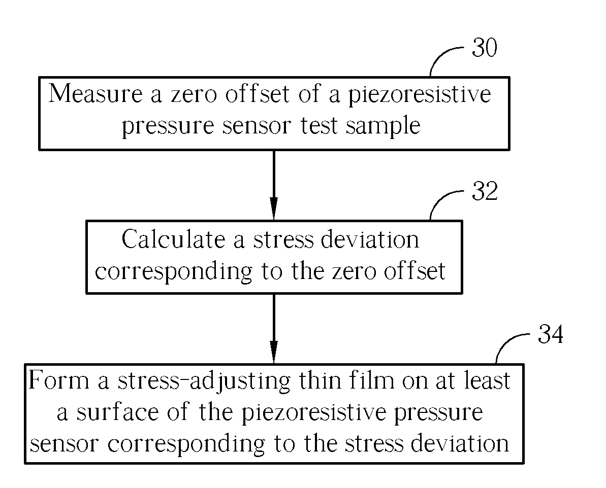
[0023] Please refer to FIG. 4. FIG. 4 is a general flow chart showing a method of calibrating a zero offset according to the present invention. As shown in FIG. 4, the steps of the present invention for calibrating a zero offset of piezoresistive pressure sensors are as follows:

[0024] Step 30: First, a piezoresistive pressure sensor test sample is provided, and a zero offset of the piezoresistive pressure sensor test sample is measured.

[0025] Step 32: Subsequently, a stress deviation corresponding to the zero offset is calculated.

[0026] Step 34: Thereafter, at least a piezoresistive pressure sensor, made under the same process condition as the piezoresistive pressure sensor test sample, is formed. In the course of forming the piezoresistive pressure sensor, a stress-adjusting thin film is formed on at least a surface of the piezoresistive pressure sensor to adjust the stress of the piezoresistive pressure sensor in order to calibrate the zero offset of the piezoresistive pressure...


PUM

PropertyMeasurementUnit
Thicknessaaaaaaaaaa
Tensile propertiesaaaaaaaaaa
Stress optical coefficientaaaaaaaaaa

Abstract

A piezoresistive pressure sensor test sample is first provided, and a zero offset of the piezoresistive pressure sensor test sample is measured. Subsequently, a stress deviation corresponding to the zero offset is calculated. Thereafter, at least a piezoresistive pressure sensor under the same process condition as the piezoresistive pressure sensor test sample is formed. When forming the piezoresistive pressure sensor, at least a stress-adjusting thin film is formed on at least a surface of the piezoresistive pressure sensor to calibrate the zero offset of the piezoresistive pressure sensor.

Description

BACKGROUND OF THE INVENTION [0001] 1. Field of the Invention [0002] The present invention relates to a method of calibrating zero offset of a pressure sensor. More particularly, the present invention relates to a method of forming a stress adjusting thin film on at least a surface of a diaphragm of a pressure sensor to calibrate a zero offset of the pressure sensor. [0003] 2. Description of the Prior Art [0004] A pressure sensor is one of the familiar components of MEMS products, and a piezoresistive pressure sensor is the most common pressure sensor at present. Please refer to FIG. 1. FIG. 1 is a theoretical structure of a prior art piezoresistive pressure sensor 10. The prior art piezoresistive pressure sensor 10 has a Wheatstone bridge arrangement, and operates on the theory that the resistance of a piezoresistor changes with the pressure. As shown in FIG. 1, the Wheatstone bridge contains four variable resistors R1, R2, R3 and R4. The input voltage (Vin) is connected to two poin...

Claims


Application Information

Patent Timeline
IPC IPC(8): G01L25/00
CPCY10T29/49004G01L25/00
Inventor HUANG, TER-CHANGLIN, HUNG-YIHSU, WEN-SYANG
Owner TOUCH MICRO SYST TECH
Why Eureka
Try Eureka