
Connecting structure of rotary connector and steering angle sensor

a technology of connecting structure and steering angle sensor, which is applied in the direction of flexible/turnable line connectors, instruments, transportation and packaging, etc., can solve the problems of increasing the number of steering angle sensor parts, affecting the operation of assembling, and generating noise such as spring noise, so as to reduce the number of parts

Inactive Publication Date: 2006-12-07
ALPS ALPINE CO LTD
View PDF3 Cites 16 Cited by
  • Summary
  • Abstract
  • Description
  • Claims
  • Application Information

AI Technical Summary

Benefits of technology

[0010] The present invention has been finalized in view of the drawbacks inherent in the related art. The present invention provides a connecting structure of a rotary connector and a steering angle sensor capable of reducing noise.
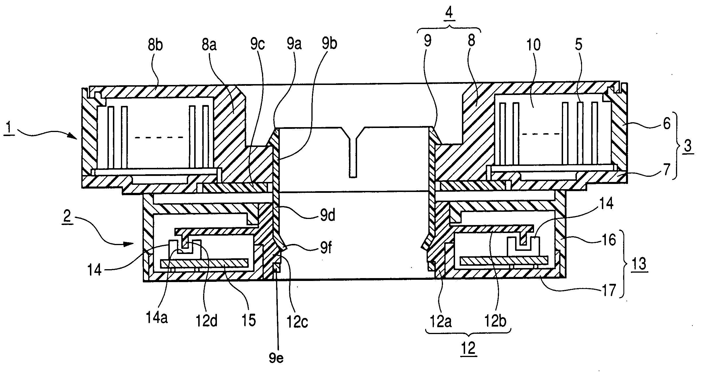
[0012] According to the solving means, both rotor members are connected to each other due to the elastic piece provided in the first rotor member being engaged with the engaging portions in the second rotor member. However, when a gap between the first rotor member and the second rotor member slightly narrows as the stator member of the rotary connector is fixedly connected to the fixing member of the steering angle sensor during the assembling, each elastic piece of the first rotor member bends. Therefore, an elastic force is applied in such a direction that the first rotor member and the second rotor member separate from each other, and the central axis of the first rotor member is allowed to deviate from the central axis of the second rotor member. In addition, when the engagement of the engaging portions prevents a backlash from occurring in the rotation direction, the first and second rotor members can be positioned in the rotation direction. Therefore, stable detection signals can be obtained from the steering angle sensor by suppressing a backlash between both rotor members, and both rotor members can be smoothly rotated, respectively, as the rotary connector which requires a relatively large clearance is connected to a highly accurate steering angle sensor.
[0013] In the above-described structure, preferably, the plurality of elastic pieces of the first rotor member are disposed at equal intervals in a circumferential direction of the inner peripheral surface of the hollow shaft portion, and at least one of the elastic pieces is positioned in a rotation direction of the second rotor member. Therefore, not only is the urging force due to the bending of each elastic piece divided equally, but also a backlash is prevented in the rotation direction between the first and second rotor members, which improves the detection accuracy of the steering angle sensor.
[0015] In addition, in the above-described structure, preferably, the second rotor member is formed of a synthetic resin molding product in which the code plate is integrally formed to the outer peripheral surface of the hollow shaft portion. Therefore, it is possible to reduce the number of parts and the man-hour for assembling.

Problems solved by technology

However, with the coil spring interposed between the rotor members, both of the rotor members should be connected to each other Consequently, operability in assembling deteriorates when the rotary connector and the steering angle sensor are formed as one unit, and noise such as a spring noise is generated due to vibration of the coil spring while driving the vehicle.
Therefore, at least three members (code plate and the pair of separate members) are required to form an integrated product including the code plate and the rotor member, which leads to an increase in the number of parts of the steering angle sensor, thereby increasing cost.

Method used


Image

  • Connecting structure of rotary connector and steering angle sensor
  • Connecting structure of rotary connector and steering angle sensor
  • Connecting structure of rotary connector and steering angle sensor

Examples


Embodiment Construction

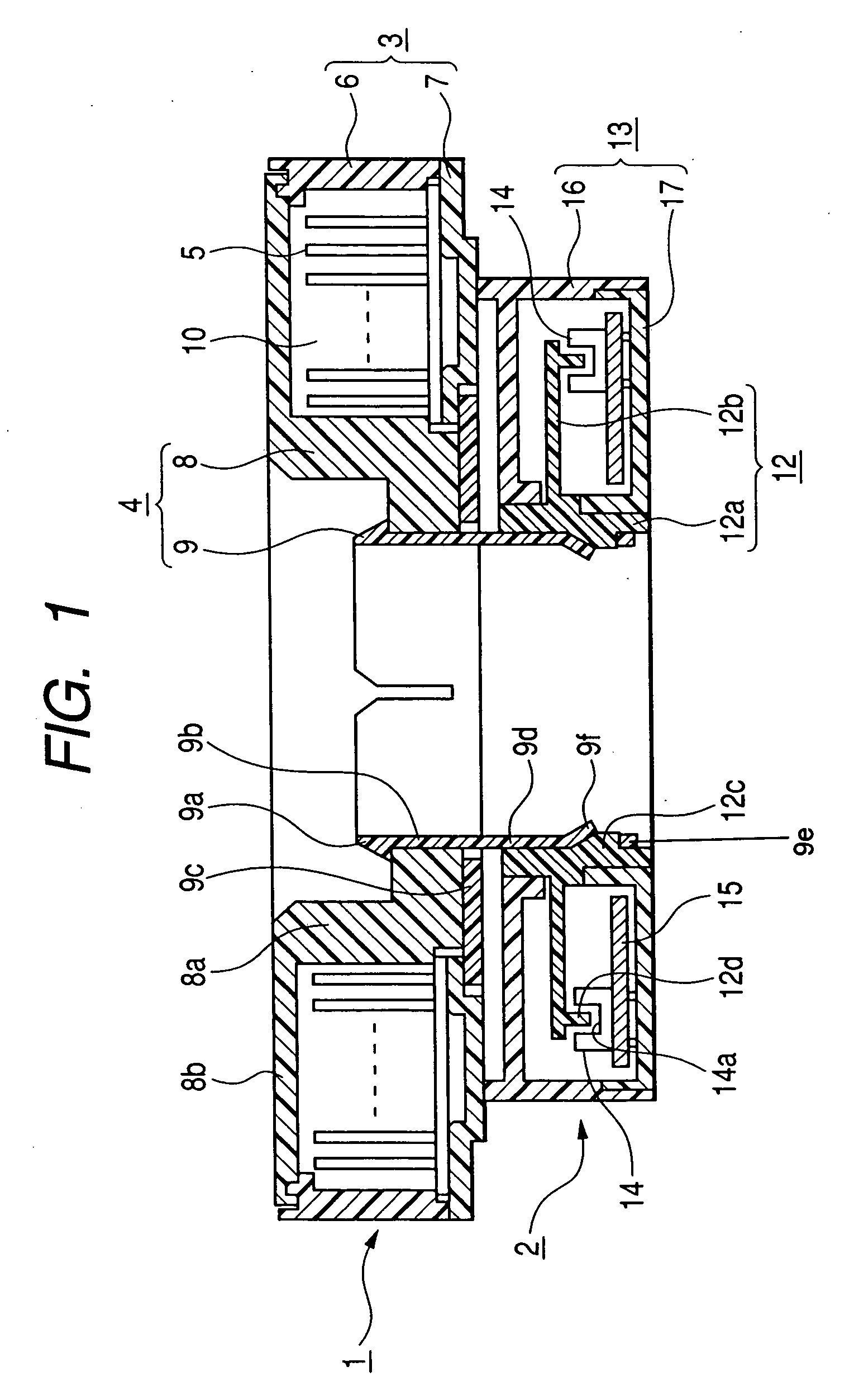
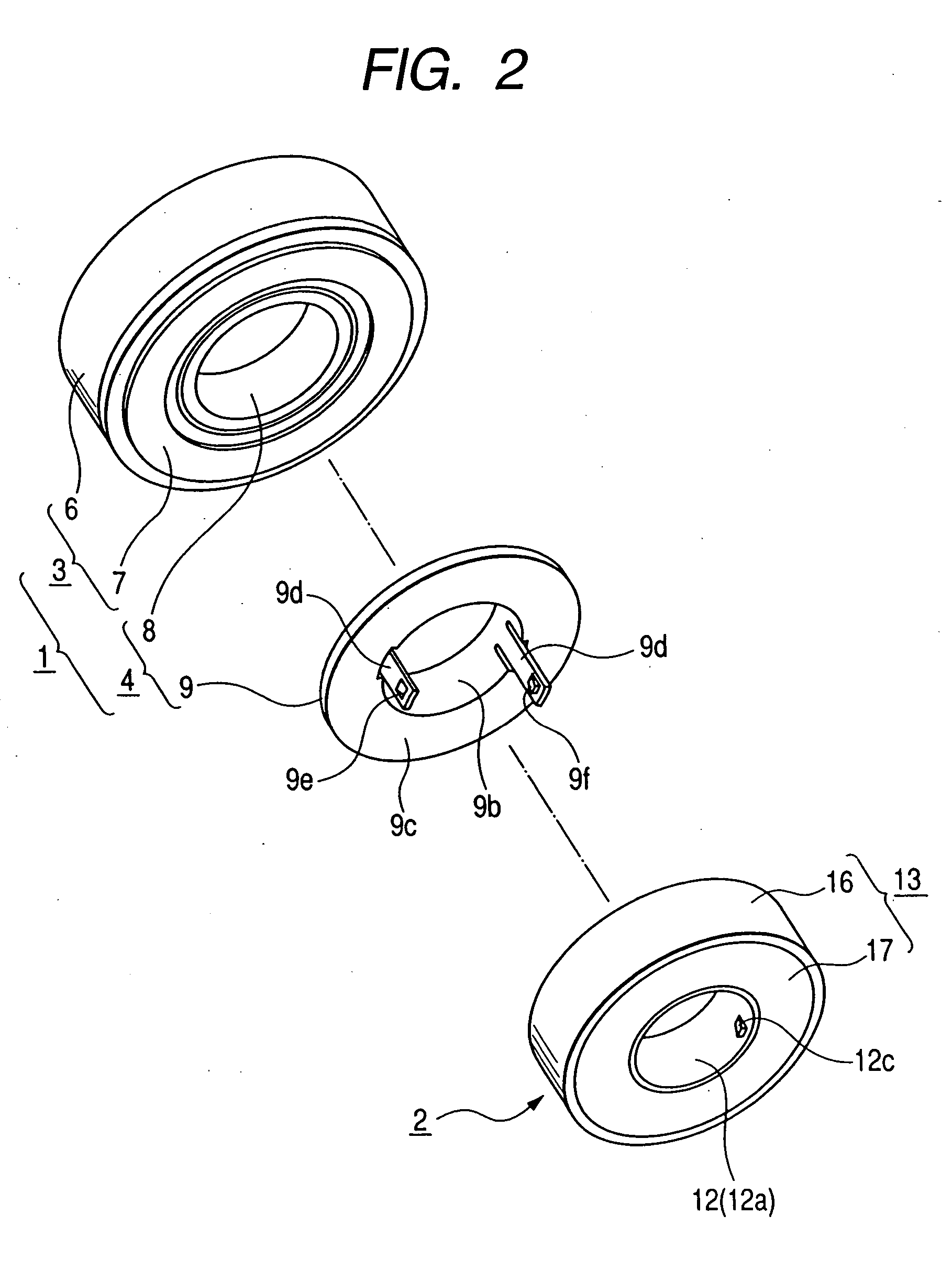
[0021] A preferred embodiment of the present invention will be described with reference to the accompanying drawings. FIG. 1 is a cross-sectional view illustrating a connecting unit of a rotary connector and a steering angle sensor according to the embodiment of the present invention. FIG. 2 is an exploded perspective view of the connecting unit. FIG. 3 is a plan view of a lower rotor provided in the connecting unit on the rotary connector side. FIG. 4 is a cross-sectional view of the lower rotor.

[0022] The connecting unit according to the embodiment is composed of a rotary connector 1 and a steering angle sensor 2. To be described below, the rotary connector 1 and the steering angle sensor 2 are built in a steering apparatus of a vehicle in an integrated state in which they are vertically laid on each other.

[0023] The rotary connector 1 is used as the electrical connecting means for an air bag system mounted on a steering wheel. The rotary connector 1 includes: a stator housing 3...


PUM

PropertyMeasurementUnit
inclined angleaaaaaaaaaa
flexibleaaaaaaaaaa
elastic forceaaaaaaaaaa

Abstract

Ae connecting structure of a first rotor member (rotor housing) of a rotary connector and a second rotor member (rotary member) of a steering angle sensor is provided. A plurality of elastic pieces are formed on the inner peripheral portion of the first rotor member and extend downward. An engaging protrusion is provided in the inner peripheral portion of the second rotor member so as to be inserted in an engaging hole of the elastic piece, and the elastic piece is combined with the engaging protrusion in a snap-in relationship.

Description

BACKGROUND OF THE INVENTION [0001] 1. Field of the Invention [0002] The present invention relates to a connecting structure of a rotary connector built in a steering apparatus of a vehicle, and a steering angle sensor. [0003] 2. Description of the Related Art [0004] A rotary connector generally includes a stator member, a rotor member rotatably connected to the stator member, a flexible cable held and wound in an annular space defined between the stator member and the rotor member, and as the rotor member is rotated in accordance with the steering wheel, the flexible cable is wound or unwound in the annular space. A relatively large clearance (in an in-plane direction orthogonal to a rotation axis) is formed between the rotor member and the stator member of the rotary connector. Accordingly, the rotor member can be stably rotated in accordance with the steering wheel. In the meantime, a steering angle sensor includes a fixing member, a rotor member having a code plate that is rotata...

Claims


Application Information

Patent Timeline
Patent Type & Authority Applications(United States)
IPC IPC(8): G01L3/14
CPCB60R16/027H01R35/025B62D15/022H01R35/04
Inventor ARAKI, JUNJISANO, TADASHI
Owner ALPS ALPINE CO LTD
Learn More