Railroad hopper car door actuating mechanism

Inactive Publication Date: 2006-12-07
TAYLOR FRED J
View PDF21 Cites 19 Cited by
  • Summary
  • Abstract
  • Description
  • Claims
  • Application Information

AI Technical Summary

Benefits of technology

[0010] It is therefore an object of the present invention to provide an actuating mech

Problems solved by technology

There are several disadvantages to the hopper door operating mechanisms described in some of the aforementioned patents.
One problem is that some of the prior art mechanisms are designed such that each actuating mechanism is connected to doors from two separate hoppers.
Another disadvantage of some of the above described hopper door mechanisms is that the operating mechanisms limit the distance of the door motion,

Method used


Image

  • Railroad hopper car door actuating mechanism
  • Railroad hopper car door actuating mechanism
  • Railroad hopper car door actuating mechanism

Examples


Example

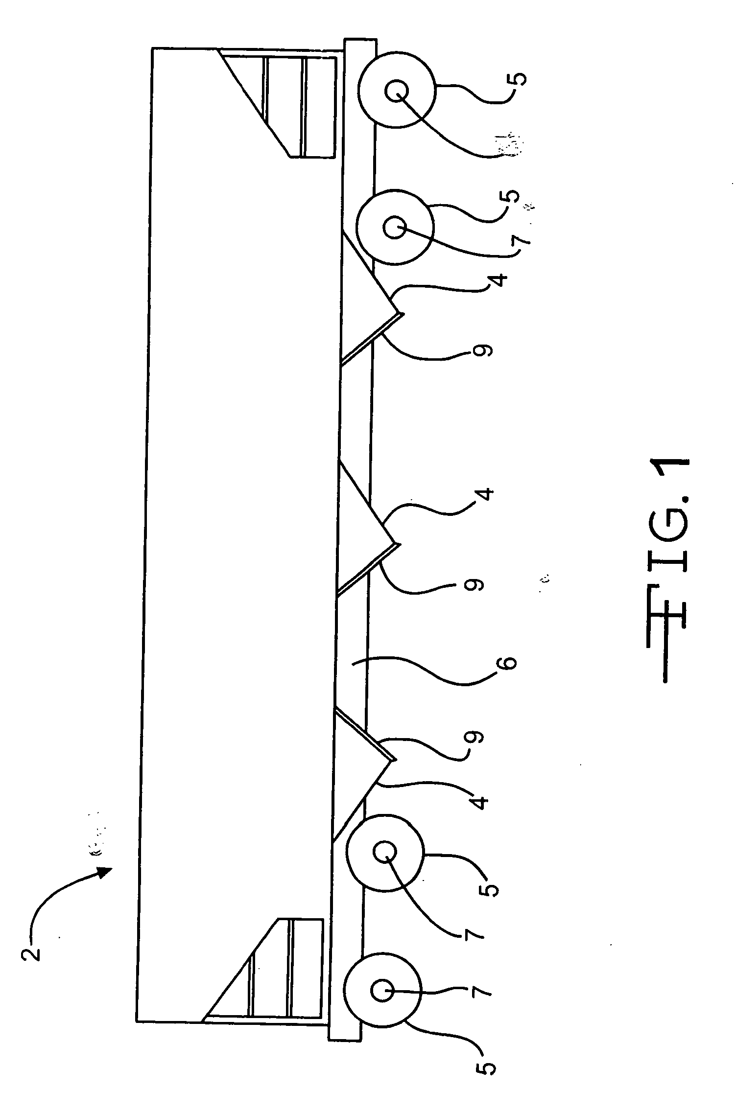
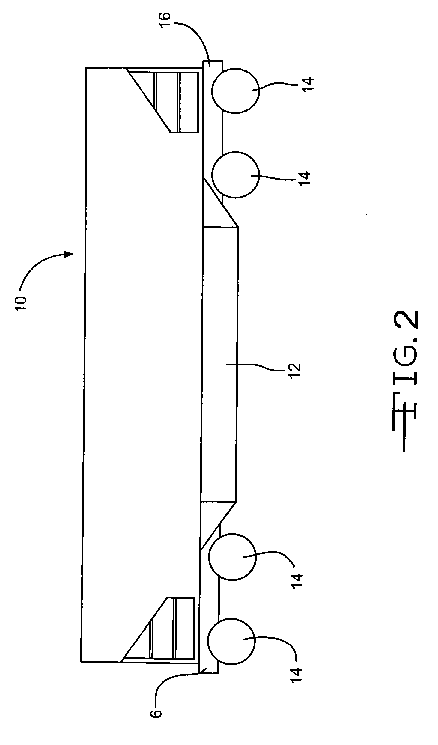
[0037]FIGS. 1-2 display two different major types of hopper cars. FIG. 1 shows hopper cars using transverse doors, while FIG. 2 shows a car using longitudinal doors.

[0038] Referring now to FIG. 1, there is shown a typical three pocket railway hopper car, generally designated at 2, which may be equipped with a preferred embodiment of the present invention. Car 2 is provided with a plurality of hopper units 4, a plurality of wheels 5, and a longitudinally extending center sill 6. Wheels 5 are mounted on a series of truck axles 7. Each hopper unit 4 is provided with a door 9 which is moveable to open and close each hopper unit 4. An actuating system for this type of car is taught in U.S. patent application Ser. No. 10 / 863,887, filed Jun. 8, 2004, which application is incorporated herein by reference.

[0039] Referring now to FIG. 2, there is shown a typical hopper railcar, generally indicated at 10, having longitudinal doors which may be equipped with a preferred embodiment of the pres...


PUM


Abstract

An actuating system for operating the doors of a railroad hopper car while dumping the contents outside of the rails. A main lever is rotatably coupled within the center sill with a rod extending from an arm of the lever to a door which covers the hopper. As the lever is rotated, the rods act to move the doors away from the hoppers.

Description

CROSS REFERENCE TO RELATED APPLICATIONS [0001] This application claims benefit from U.S. Provisional Patent Application Ser. Nos. 60 / 687,081, filed Jun. 3, 2005, and 60 / 691,484, filed Jul. 2, 2005 which applications are incorporated herein by reference.BACKGROUND OF THE INVENTION [0002] 1. Field of the Invention [0003] The present invention is directed in general to a device for opening the hopper doors of a railroad car, and, in particular, to a system for automatically opening and closing the hopper doors of a railroad car. [0004] 2. Description of the Related Art [0005] A common type of railroad freight car in use today is the freight car of the type wherein the load is discharged through hoppers in the underside of the body. Such cars are generally referred to as hopper cars and are used to haul coal, phosphate and other commodities. [0006] After hopper cars are spotted over an unloading pit, the doors of the hoppers are opened, allowing the material within the hopper to be empt...

Claims


Application Information

Patent Timeline
IPC IPC(8): B61D3/00
CPCB61D7/24
Inventor TAYLOR, FRED J.
Owner TAYLOR FRED J
Why Eureka
Try Eureka