Connecting link assembly and socket arrangement for assembly of floating drive-on dry docks

a technology of connecting link and socket arrangement, which is applied in the direction of special-purpose vessels, vessel construction, transportation and packaging, etc., can solve the problems of unsuitable decks or walkways, poor guiding surface of most boat hull construction, and unsuitable for pedestrian traffic, so as to achieve the effect of adding strength and rigidity to the connecting link

Inactive Publication Date: 2006-12-07
RUECKERT DAVID
View PDF27 Cites 25 Cited by
  • Summary
  • Abstract
  • Description
  • Claims
  • Application Information

AI Technical Summary

Benefits of technology

[0023] In one embodiment a structural floating deck element is preferably a polyhedron in overall shape including a first, generally planar, upper surface adapted for use as a deck, a second lower surface and a plurality of side walls for adjoining and maintaining spacing between the first surface and the second surface. A plurality of socket apertures may extend around the perimeter of the deck element in predetermined intervals for attachment to adjacent floating elements. The inner cavity of the floating deck element may be filled with expanded polymeric material, e.g. foam, to provide rigidity to the deck element and / or buoyancy in the event that one of the surfaces or side walls are breached. Alternatively, the inner cavity of the floating deck element may be partially filled with ballast to change the floating characteristics of the dock and / or deck.
[0029] The sockets in both the deck and dock elements are arranged to align with at least one socket of an adjacent deck and / or dock element. In a preferred embodiment at least two sockets are arranged for alignment with at least two sockets within adjacent deck and / or dock elements. The sockets each preferably include an aperture, a contoured upper pocket and a contoured lower pocket. The contoured upper and lower pockets in the preferred embodiment have sufficient depth to create a substantially flat upper surface when the connecting links are installed. In alternative embodiments the depth of the upper or lower pockets may be adjusted to permit uneven or stepped upper surfaces between adjacent deck and / or dock elements. The aperture extends through the dock or deck element and is preferably round having sufficient diameter to accept a standard four inch diameter pvc pipe. This construction permits the socket aperture to be used for securing the deck or dock elements to a stationary structure while allowing the elements to rise and fall with tides and water levels.
[0030] The connecting link includes a lower portion and an upper portion. The lower portion includes a lower plate and a pair of upstanding integrally formed pins. An integrally formed rib extends between the upward standing pins to add strength and rigidity to the connecting link. The upper portion of the link includes an upper plate, the upper plate includes a pair of apertures. The apertures are arranged to permit the upper plate to be secured to the upward standing pins of the lower portion via fasteners.
[0035] An additional objective of the instant invention is to provide floating deck and dock elements which can be assembled into a substantially rigid drive-on dock assembly that provides increased safety by not requiring open wells or gaps between floatation elements for drive-on operation.
[0037] Still another objective of the instant invention is to provide floatable deck and dock elements which include internal cavities filled with expanded polymeric foam to provide rigidity to the dock or deck elements and buoyancy in the event of an element breach.

Problems solved by technology

This construction also causes instability and makes the units difficult to walk along.
This construction provides a poor guiding surface for most boat hull constructions.
In addition, the narrow width of the floatation units and the flexible connections associated therewith make these structures extremely unstable for pedestrian traffic and unsuitable for decks or walkways.
This safety hazard is magnified when the docks are used at night or in rough waters.
Still further, the open wells within these dock assemblies combined with the wave action associated with large bodies of water often results in repeated splashing of water into the drive units of the docked watercraft and thus causes premature failure of important components of the watercraft drive system.
In addition to the shortcomings described above, the air systems utilized within these devices are complex and significantly increase the initial cost of the dock.
In addition, cost of maintaining the air and water pumps in a marine environment is increased, while reliability of the systems is decreased.

Method used


Image

  • Connecting link assembly and socket arrangement for assembly of floating drive-on dry docks
  • Connecting link assembly and socket arrangement for assembly of floating drive-on dry docks
  • Connecting link assembly and socket arrangement for assembly of floating drive-on dry docks

Examples


Embodiment Construction

[0049] It is to be understood that while a certain form of the invention is illustrated, it is not to be limited to the specific form or arrangement of parts herein described and shown. It will be apparent to those skilled in the art that various changes may be made without departing from the scope of the invention and the invention is not to be considered limited to what is shown in the drawings and described in the specification.

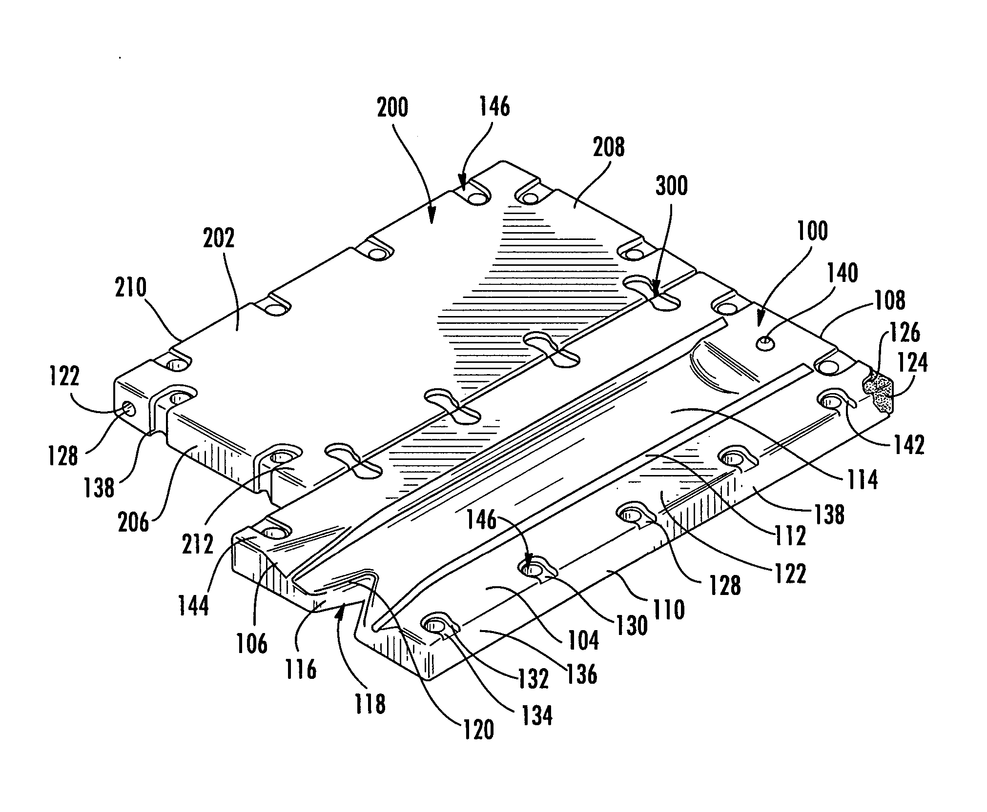
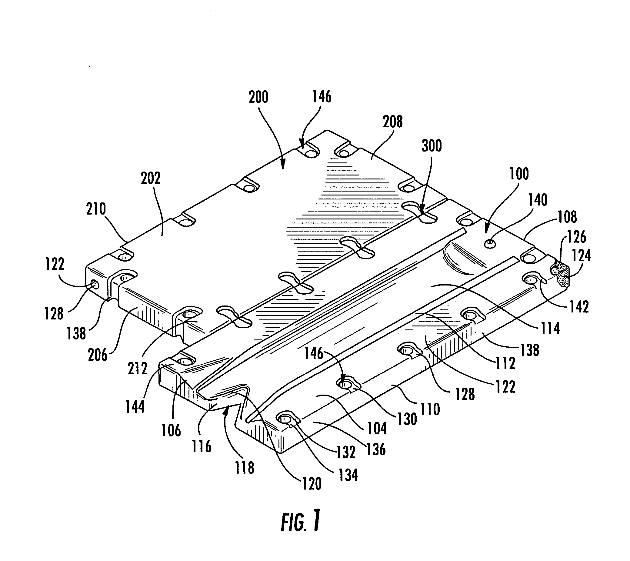
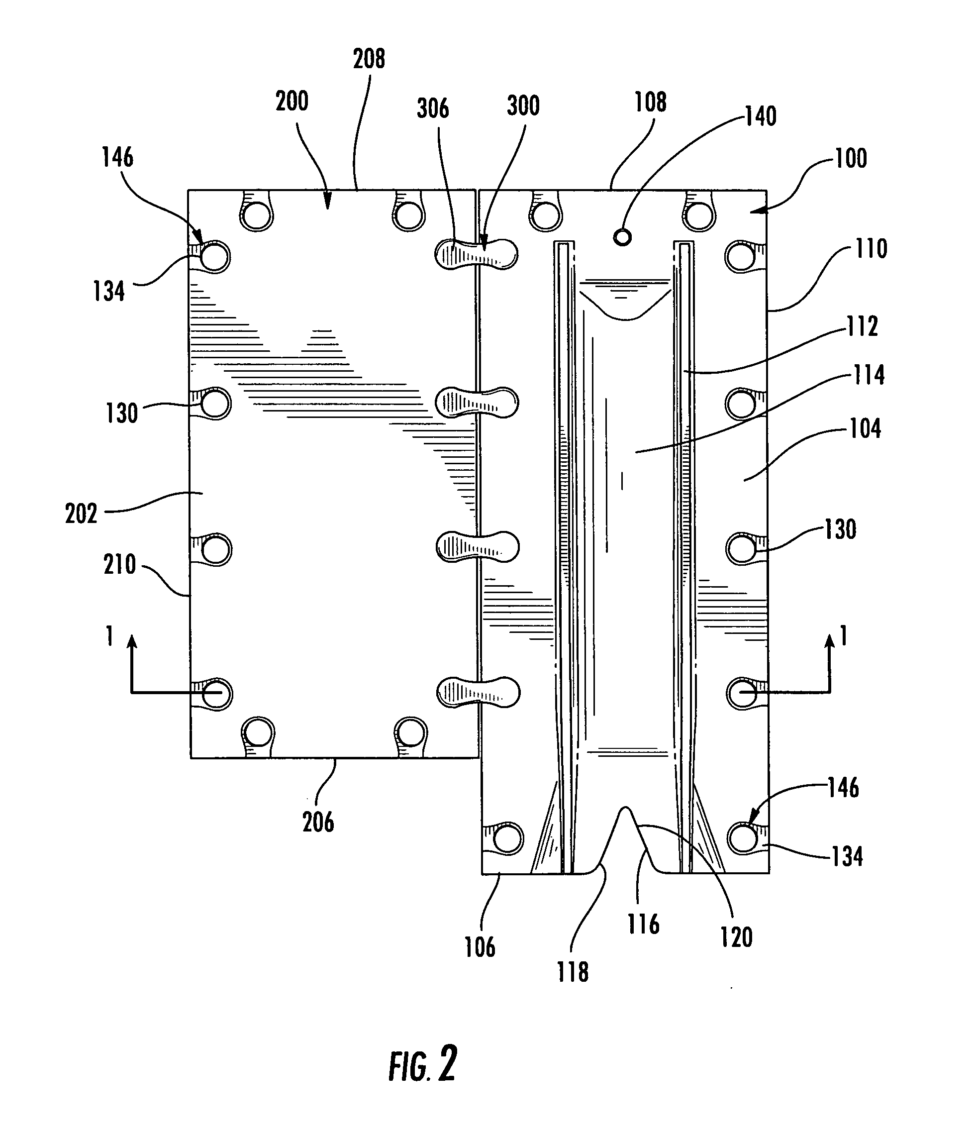
[0050] With reference to FIGS. 1 through 3, the instant invention provides a floating dock element 100, a floating deck element 200 and a connecting link assembly 300. The floating dock element 100 in its preferred embodiment is generally rectangular in overall shape, including a lower generally planar surface 102, an upper receiving surface 104, a front wall 106, a back wall 108, and a pair of side walls 110 for adjoining and maintaining spacing between the upper surface and the lower surface. The upper receiving surface 104 includes two upward standing ...


PUM


Abstract

The present invention provides a connecting link assembly and socket arrangement for assembling modular dock and / or deck elements into walkways, decks and drive-on docks.

Description

FIELD OF THE INVENTION [0001] This invention is directed to floating drive-on dry docks and, in particular, to a connecting link and socket arrangement for connecting floating structural members into substantially rigid floating drive-on dry docks and floating decks. BACKGROUND OF THE INVENTION [0002] In the past, modular floating docks have been created by the assembly of a number of floating subunits. These subunits include various geometric shapes with planar upper and lower surfaces. The subunits connect together to create flexible docks and walkways having various shapes and sizes based on the consumers needs. [0003] For example, U.S. Pat. Nos. 3,824,644 and 4,604,962 disclose a substantially prismatic, floating element having rounded corner edges. The elements are provided with outwardly projecting eye lugs for flexible attachment to adjacent elements. [0004] U.S. Pat. No. 4,655,156 discloses a stackable floating element. The elements include alternating rectangular projection...

Claims


Application Information

Patent Timeline
Patent Type & Authority Applications(United States)
IPC IPC(8): B63B35/44
CPCB63B3/08B63B3/06
Inventor RUECKERT, DAVID
Owner RUECKERT DAVID
Why Eureka
Try Eureka