Photovoltaic concentrator for solar energy system

a solar energy system and photovoltaic concentrator technology, applied in the direction of pv power plants, light radiation electric generators, generators/motors, etc., can solve the problems of high cost, bulky traditional optical concentrators used for higher optical concentration, and need active tracking of light rays

Active Publication Date: 2006-12-07
GENERAL ELECTRIC CO
View PDF17 Cites 125 Cited by
  • Summary
  • Abstract
  • Description
  • Claims
  • Application Information

AI Technical Summary

Problems solved by technology

Traditional optical concentrators used for higher levels of optical concentration are often bulky and require

Method used


Image

  • Photovoltaic concentrator for solar energy system
  • Photovoltaic concentrator for solar energy system
  • Photovoltaic concentrator for solar energy system

Examples


Embodiment Construction

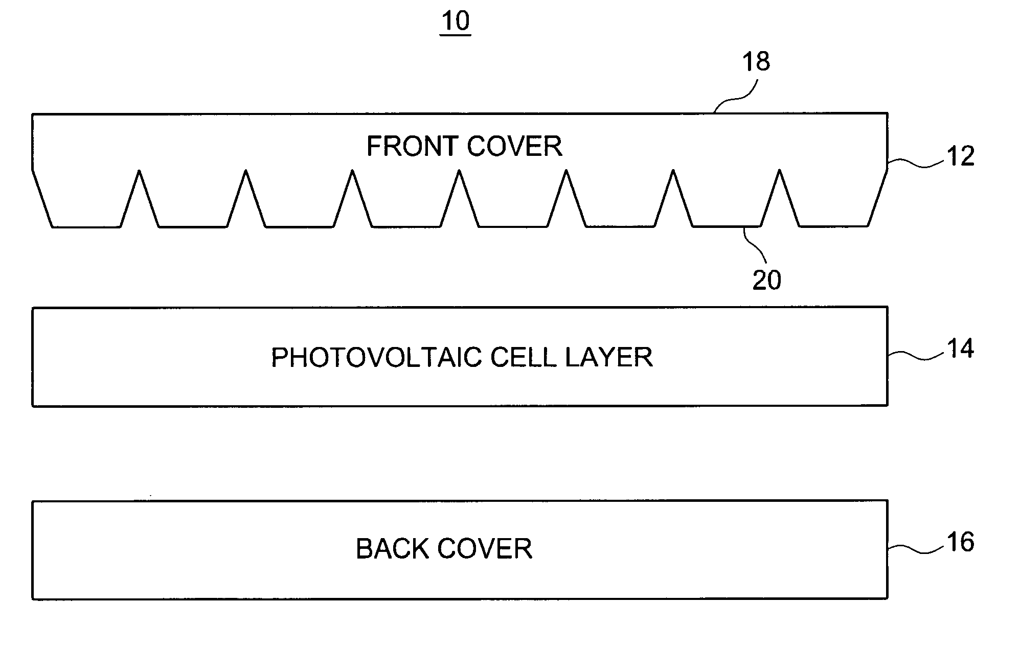
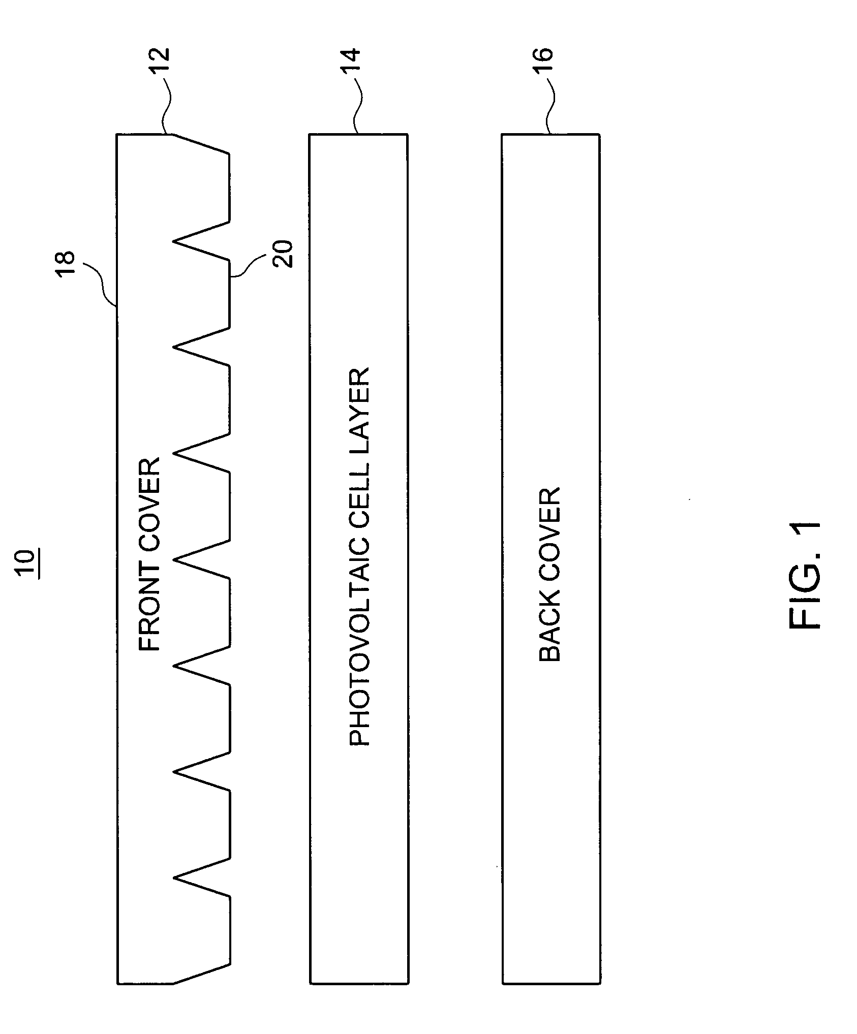
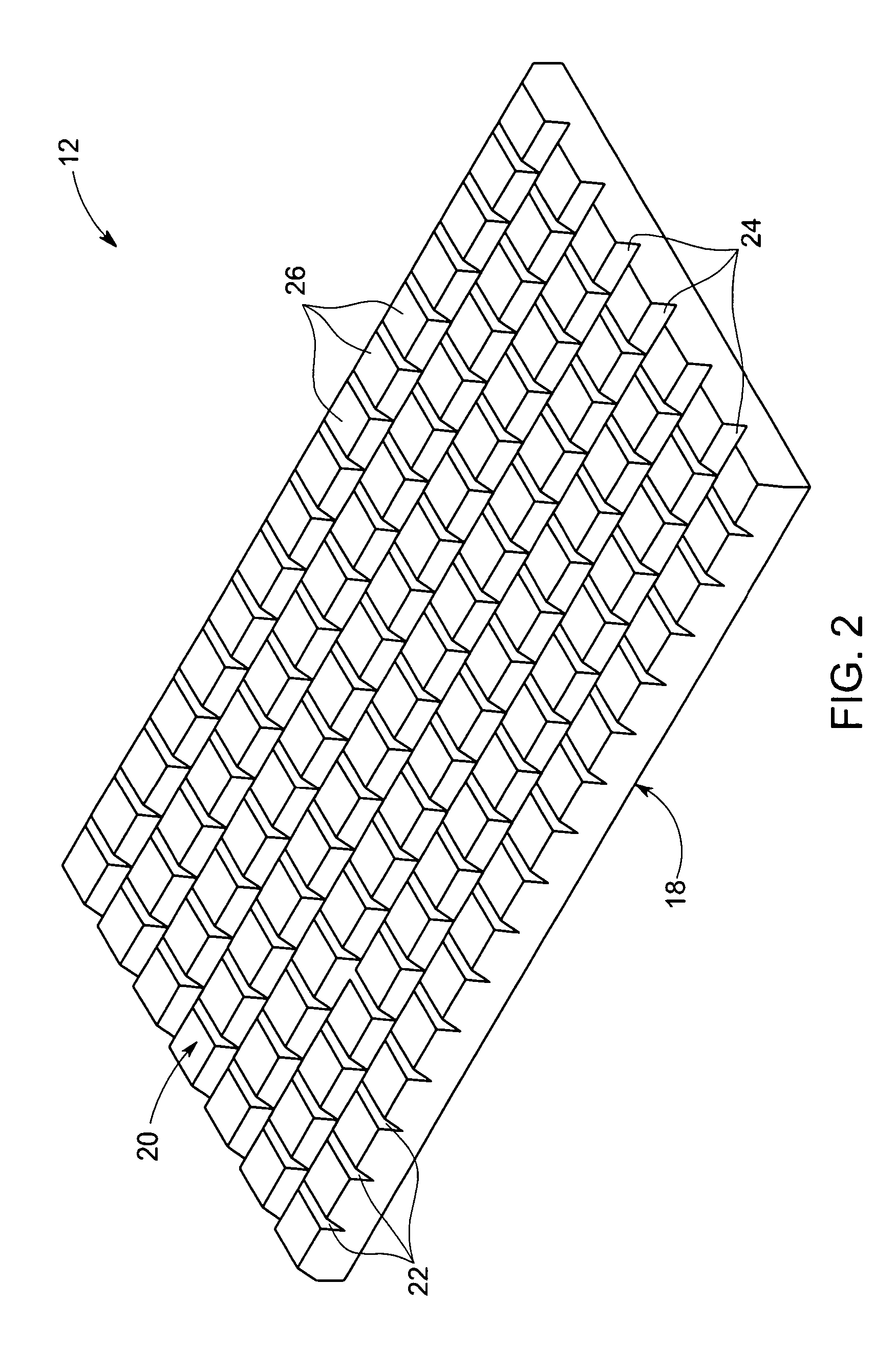
[0022] As discussed in detail below, embodiments of the present technique provide an energy conversion system having a solar concentrator configured to receive solar energy and further configured to concentrate and guide the solar energy to a photovoltaic cell layer. The solar concentrator is configured to accept light rays from a broad range of incident flux angles with minimal degradation in performance. Specifically, the solar concentrator comprises a front cover having a patterned surface configured to concentrate and guide the solar energy. In accordance with the present technique, cost per power ratio of the solar concentrator is reduced. Also techniques are disclosed in which solar energy incident on the photovoltaic cell layer is directly transmitted through the above-mentioned solar concentrator or is transmitted by total internal reflection through the solar concentrator or a combination thereof. Various embodiments of these techniques are discussed in further detail below...


PUM


Abstract

The energy conversion system includes a first optical cover having a flat surface and a patterned surface. The patterned surface is configured to receive solar energy from the flat surface, then concentrate and guide the solar energy. The system also includes a second optical cover. The system further includes providing a photovoltaic cell layer between the patterned surface of the first optical cover and the second optical cover. The photovoltaic cell layer is configured to receive the solar energy from the patterned surface and convert the solar energy into electrical energy.

Description

BACKGROUND [0001] The invention relates generally to a solar energy conversion system, and more particularly, to a photovoltaic concentrator configured to concentrate and guide incident light onto plurality of photovoltaic cells. [0002] Solar energy is considered as an alternate source of energy relative to other forms of energy. Solar energy conversion systems are used to convert solar energy into electrical energy. The solar energy conversion system typically includes photovoltaic modules, photoelectric cells, or solar cells that convert solar energy into electrical energy for immediate use or for storage and subsequent use. Conversion of solar energy into electrical energy includes reception of light, such as sunlight, at a solar cell, absorption of sunlight into the solar cell, generation and separation of positive and negative charges creating a voltage in the solar cell, and collection and transfer of electrical charges through a terminal coupled to the solar cell. [0003] Sola...

Claims


Application Information

Patent Timeline
IPC IPC(8): H02N6/00
CPCH01L31/042H01L31/0547Y02E10/52
Inventor DURVASULA, RAVI SHANKAR
Owner GENERAL ELECTRIC CO
Why Eureka
Try Eureka