Compositions and processes for format flexible, roll-to-roll manufacturing of electrophoretic displays

Inactive Publication Date: 2005-03-29
E INK CALIFORNIA
View PDF8 Cites 52 Cited by
  • Summary
  • Abstract
  • Description
  • Claims
  • Application Information

AI Technical Summary

Benefits of technology

The fourth aspect of the present invention is directed to the use of the stripping process and strippable composition in combination with the strip or patch coating/embossing processes to improve the yield and throughp

Problems solved by technology

In other words, the display panels are laminated piece by piece; thus the process has a very low throughput.
However, either process has at least four major disadvantages: (1) a sophisticated coating on the first substrate with precision tracking and metering of the embossing composition is needed to define the edge and also to avoid undesirable resin coverage onto the areas having exposed electrode lines or patterns; (2) uneven edge thickness and profile are produced because the embossable composition tends to be squeezed out side-ways during embossing under pressure; (3) the shape and dimension of the display are predefined by the strip or patch coating process; and

Method used


Image

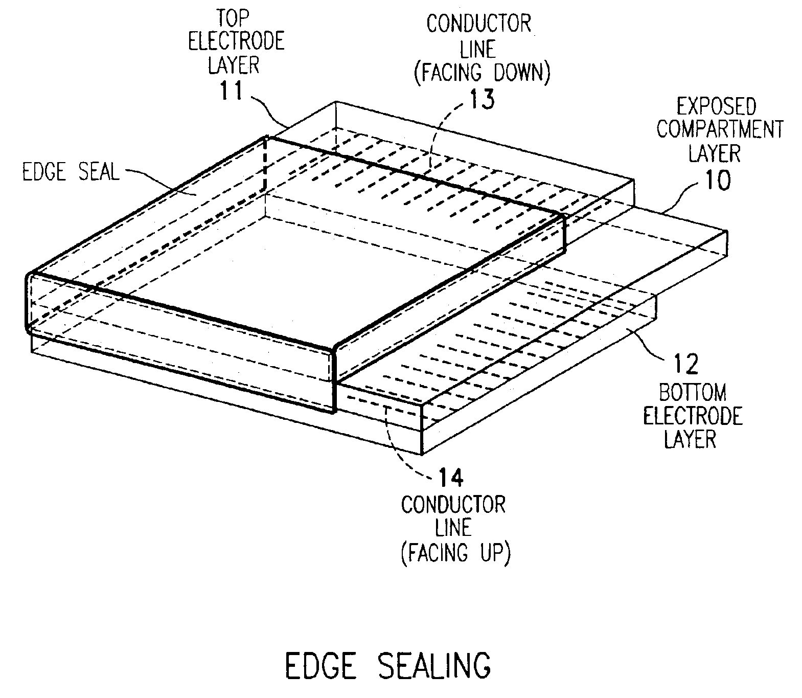
  • Compositions and processes for format flexible, roll-to-roll manufacturing of electrophoretic displays
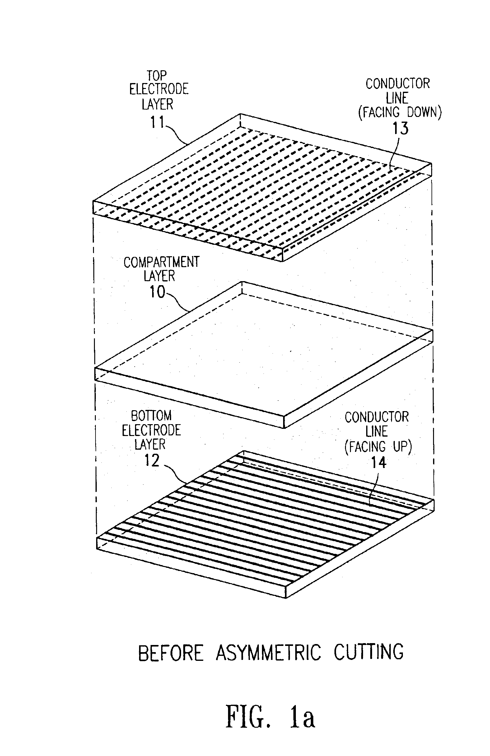
  • Compositions and processes for format flexible, roll-to-roll manufacturing of electrophoretic displays
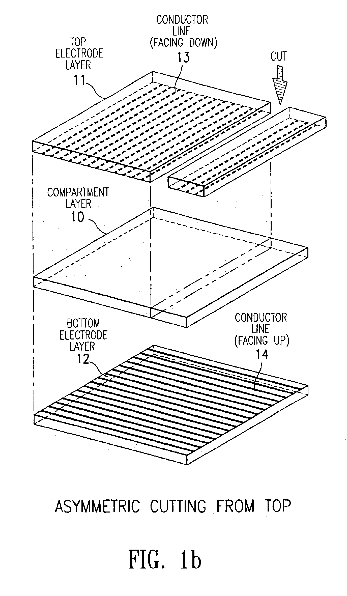
  • Compositions and processes for format flexible, roll-to-roll manufacturing of electrophoretic displays

Examples


example 1

I. Preparation of Strippable Primer Composition

Solution (a)

33.2 Grams of EB 600™ (UCB, Smyrna, Ga.), 16.12 gm of SR 399™ (Sartomer, Exton, Pa.), 16.12 gm of TMPTA (UCB, Smyrna, Ga.) and 20.61 gm of HDODA (UCB, Smyrna, Ga.) were added into a 250 gm plastic round bottle. The mixture was stirred with a general purpose blade at 500 RPM for 30 minutes.

Solution (b)

2 Grams of lrgacure™ 369 (Ciba, Tarrytown, N.Y.) and 1 gm of Irganox™ 1035 were combined into a glass bottle containing 10 gm of MEK (Fisher, Pittsburgh, Pa.). The mixture was sonicated (FS-220H, Fisher, Pittsburgh, Pa.).

Solution (c)

44.35 Grams of polyethylmethacrylate (Aldrich, Milwaukee, Wis.) and 389.15 gm of MEK were combined into a 1 liter plastic bottle and the mixture was stirred with a 1″ general purpose blade at 500 rpm for 60 minutes.

Solutions (a) and (b) prepared above were added into solution (c) contained in a 1 liter bottle, and the mixture was stirred with a 1″ general purpose blade at 500 rpm for 30 minutes. This...

example 2

The procedure of Example 1 was followed except that the UV-strippable adhesive used in section I was replaced by a pressure sensitive adhesive Dura-tak-1105 (National Starch and Chemical Co., Bridgewater, N.J.) and the UV curing step was skipped in the lamination step. The resulting device was tested and found to have adequate contrast at low voltages.

example 3

The procedure of Example 1 was followed, except that in the preparation of the strippable primer layer composition in section I, polyethylmethacrylate (Aldrich, Milwaukee, Wis.) was replaced with Carboset 515 (BF Goodrich, Cleveland, Ohio).


PUM

PropertyMeasurementUnit
Solubility (mass)aaaaaaaaaa
Areaaaaaaaaaaa
Mechanical propertiesaaaaaaaaaa

Abstract

The present invention is directed to a process which comprises removing and stripping off part of the display panel in order to expose and connect the conductor lines on an electrode plate to a driver circuitry. More specifically the process involves (1) preparing a display panel having filled display cells sandwiched between a first and a second substrate layers, preferably by a roll-to-roll process; (2) removing part of a first substrate by asymmetrical cutting by, for example, a die, diamond, knife or laser cutting method to expose the layers underneath (which may include adhesive layer, primer layer, display cell layer and in the case of a display prepared by the microcup technology, the microcup layer and the sealing layer); and (3) stripping off the exposed layers by a stripping solvent or solution. After stripping, the conductor lines on the second substrate are exposed and ready for connection to the driver circuitry.

Description

BACKGROUND OF THE INVENTION1. Field of the InventionThe invention is directed to compositions and processes useful for the roll-to-roll manufacturing of electrophoretic and electromagnetophoretic displays.2. Description of Related ArtThe electrophoretic display (EPD) is a non-emissive device based on the electrophoresis phenomenon of charged pigment particles suspended in a solvent. It was first proposed in 1969. The display usually comprises two plates with electrodes placed opposing each other, separated by spacers. One of the electrodes is usually transparent. An electrophoretic fluid composed of a colored solvent with charged pigment particles dispersed therein is enclosed between the two plates. When a voltage difference is imposed between the two electrodes, the pigment particles migrate to one side or the other causing either the color of the pigment particles or the color of the solvent being seen from the viewing side.There are several different types of EPDs. In the partit...

Claims


Application Information

Patent Timeline
IPC IPC(8): G02F1/01G02F1/167B44C1/22C09K13/00G02F1/09G02F1/13
CPCG02F1/167G02F1/13452G02F2001/1672G02F2001/094G02F1/1681G02F1/094
Inventor TSENG, SCOTT C-JWU, ZARNG-ARH GEORGEWANG, XIAOJIALIANG, RONG-CHANG
Owner E INK CALIFORNIA
Why Eureka
Try Eureka