Bellows for articulated joints

Inactive Publication Date: 2006-12-07
CARL FREUDENBERG KG
View PDF6 Cites 4 Cited by
  • Summary
  • Abstract
  • Description
  • Claims
  • Application Information

AI Technical Summary

Benefits of technology

[0023] The substructure may have a frustoconical design, at least in portions thereof. The tapering of the truncated cone may be selected as a function of those angles that may be subten

Problems solved by technology

At the same time, the ridges reduce the resistance to such

Method used


Image

  • Bellows for articulated joints
  • Bellows for articulated joints
  • Bellows for articulated joints

Examples


Example

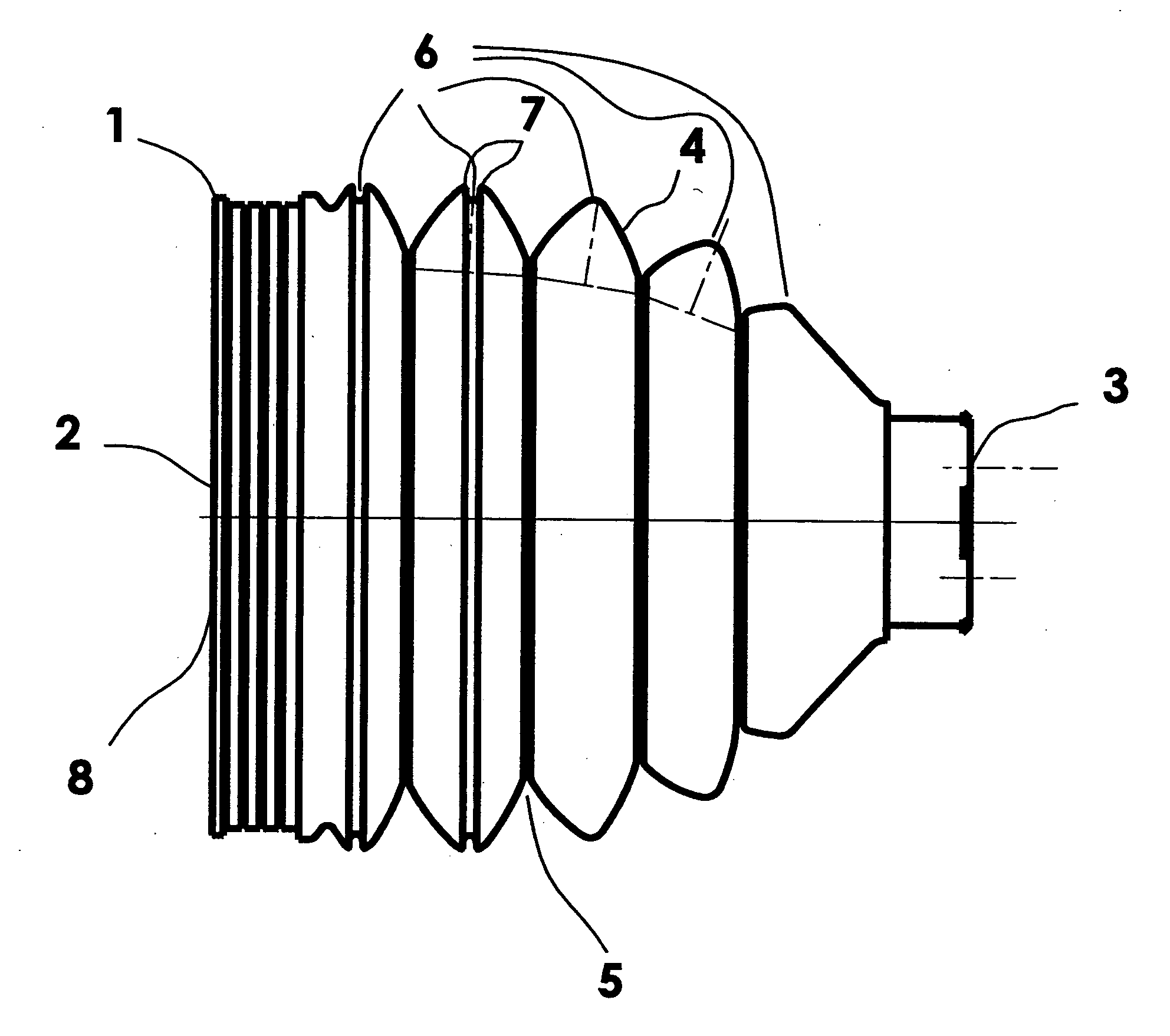
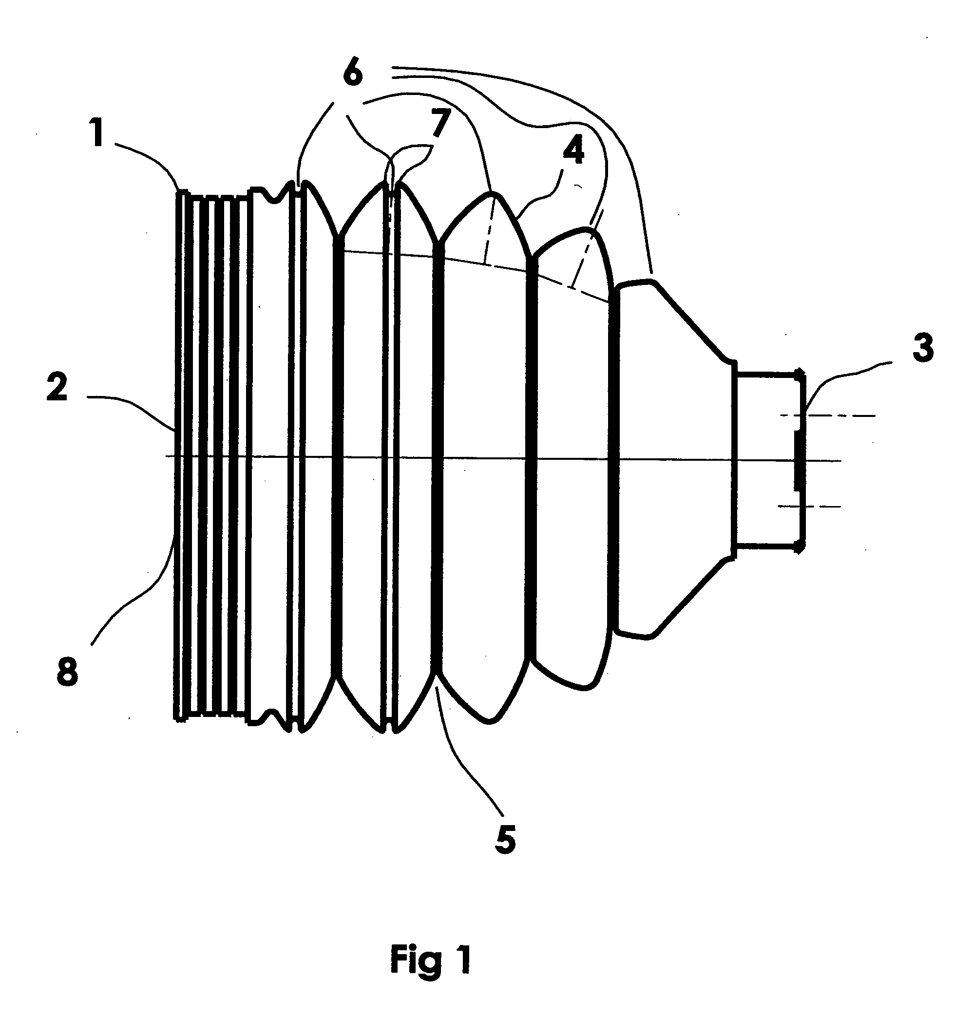
[0036]FIG. 1 shows a bellows having a substructure 1 including a first end 2 and a second end 3, ends 2, 3 being movable relative to one another, circumferential bulges 4, which are spaced apart by first constricted regions 5, being formed in substructure 1 between the ends, and a second constricted region 6 being formed in at least one bulge 4. The width of second constricted region 6 has a value that corresponds at most to the value of its depth. Second constricted regions 6 are bounded by two ridges 7. First constricted regions 5 and second constricted regions 6 are disposed concentrically about an axis extending through ends 2, 3. Second constricted regions 6 are formed in the area of the outermost circumference of bulges 4.

[0037] Substructure 1 has an axially symmetric design. Ends 2, 3 are formed as ends 2, 3 of an axial passage 8 in substructure 1. Substructure 1 has a frustoconical design, at least in portions thereof.

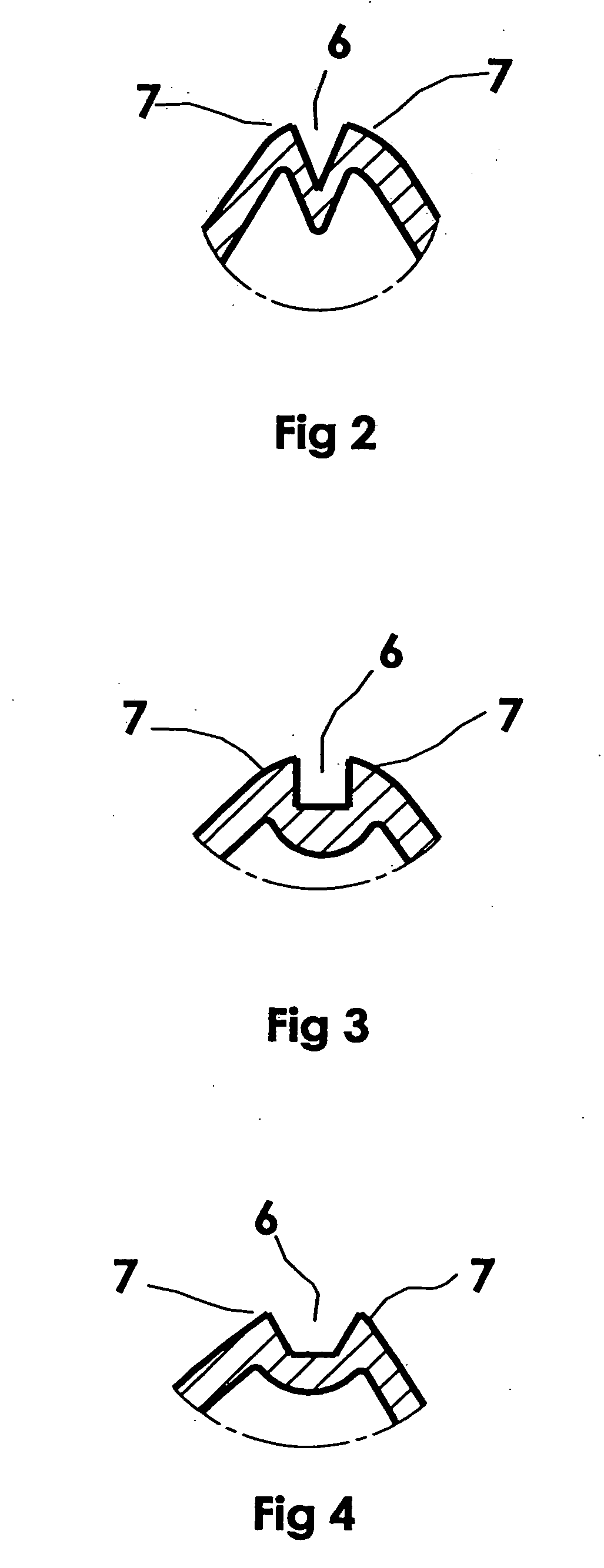
[0038]FIG. 2 shows a second constricted region that is ...


PUM


Abstract

A bellows having a substructure including a first end and a second end, the ends being movable relative to one another, circumferential bulges, which are spaced apart by first constricted regions, being formed in the substructure between the ends, and a second constricted region being formed in at least one bulge. The width of the second constricted region corresponds at least to its height in order to reduce the axial stiffness and increase the radial stiffness.

Description

[0001] This application claims the benefit of European Patent Application No. 05 011 784.5 filed Jun. 1, 2005 and hereby incorporated by reference herein. [0002] The present invention relates to a bellows having a substructure including a first end and a second end, the ends being movable relative to one another, circumferential bulges, which are spaced apart by first constricted regions, being formed in the substructure between the ends, and a second constricted region being formed in at least one bulge. BACKGROUND INFORMATION [0003] Bellows of this kind are already known from the related art. The German Patent Application No. DE 25 05 542 A1 describes a bellows of the type described, whose second constricted regions extend in a very flat and wide form. Bellows of this type are frequently assigned to articulated joints, in particular to articulated joints for drive shafts of motor vehicles. The bellows have load-bearing capacity both in the axial, as well as in the radial direction...

Claims


Application Information

Patent Timeline
IPC IPC(8): F16J15/52F16J3/00
CPCF16J3/043
Inventor SCHIRMER, STEFAN
Owner CARL FREUDENBERG KG
Why Eureka
Try Eureka