
Data encoding apparatus, data encoding method, and recording medium recorded with program

a data encoding and data technology, applied in the field of data encoding apparatus, data encoding method, recording medium recorded with program, can solve the problems of inability to decode information, inability to specify the position of the restart marker, and inability to expand the data further, so as to achieve high degree of error resistance

Active Publication Date: 2006-12-07
OM DIGITAL SOLUTIONS CORP
View PDF1 Cites 12 Cited by
  • Summary
  • Abstract
  • Description
  • Claims
  • Application Information

AI Technical Summary

Benefits of technology

[0011] An object of this invention is to provide a data encoding apparatus, a data encoding method, and a recording medium recorded with a program which are capable of attaching a control code having a high degree of error resistance.

Problems solved by technology

It is generally known that when encoded data are stored at a fixed length and an error occurs during transmission or the like, further data expansion may become impossible.
However, with a technique such as that described above, in which restart markers are embedded in Golomb-Rice encoded data as a control code using offset information, the position of the restart marker may deviate from the position indicated by the offset information due to missing data, the attachment of error information, and so on at a point in the data, and hence the position of the restart marker cannot be specified even though the restart marker exists.
As a result, it may become impossible to decode the information.
Furthermore, since the offset information takes a chain structure, damage to the position information of a certain restart marker causes similar damage to the position information of the subsequent restart markers.
Therefore, the degree of error resistance of a conventional restart marker which can be applied to Golomb-Rice encoding and so on cannot be said to be sufficiently high.

Method used


Image

  • Data encoding apparatus, data encoding method, and recording medium recorded with program
  • Data encoding apparatus, data encoding method, and recording medium recorded with program
  • Data encoding apparatus, data encoding method, and recording medium recorded with program

Examples


first embodiment

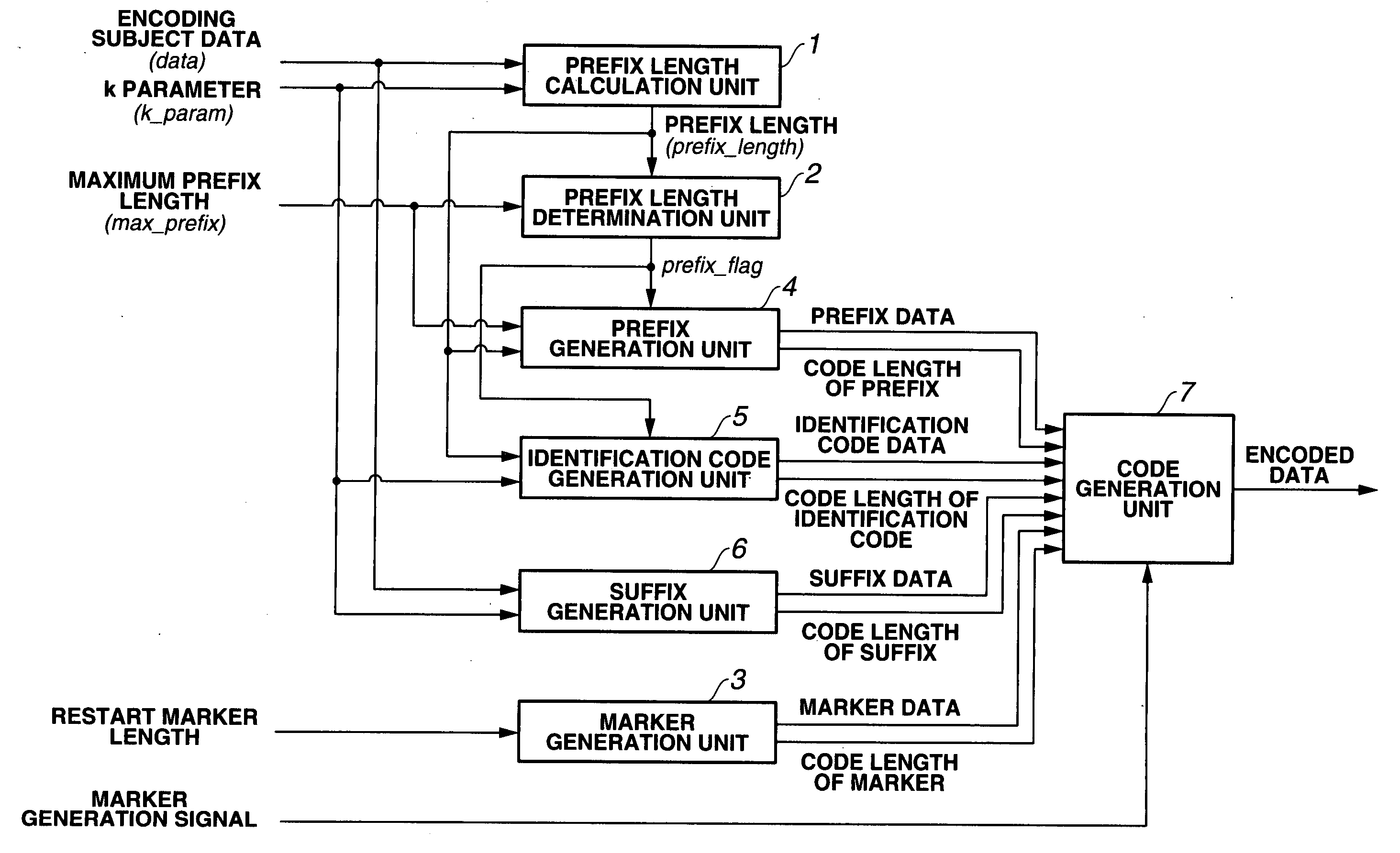
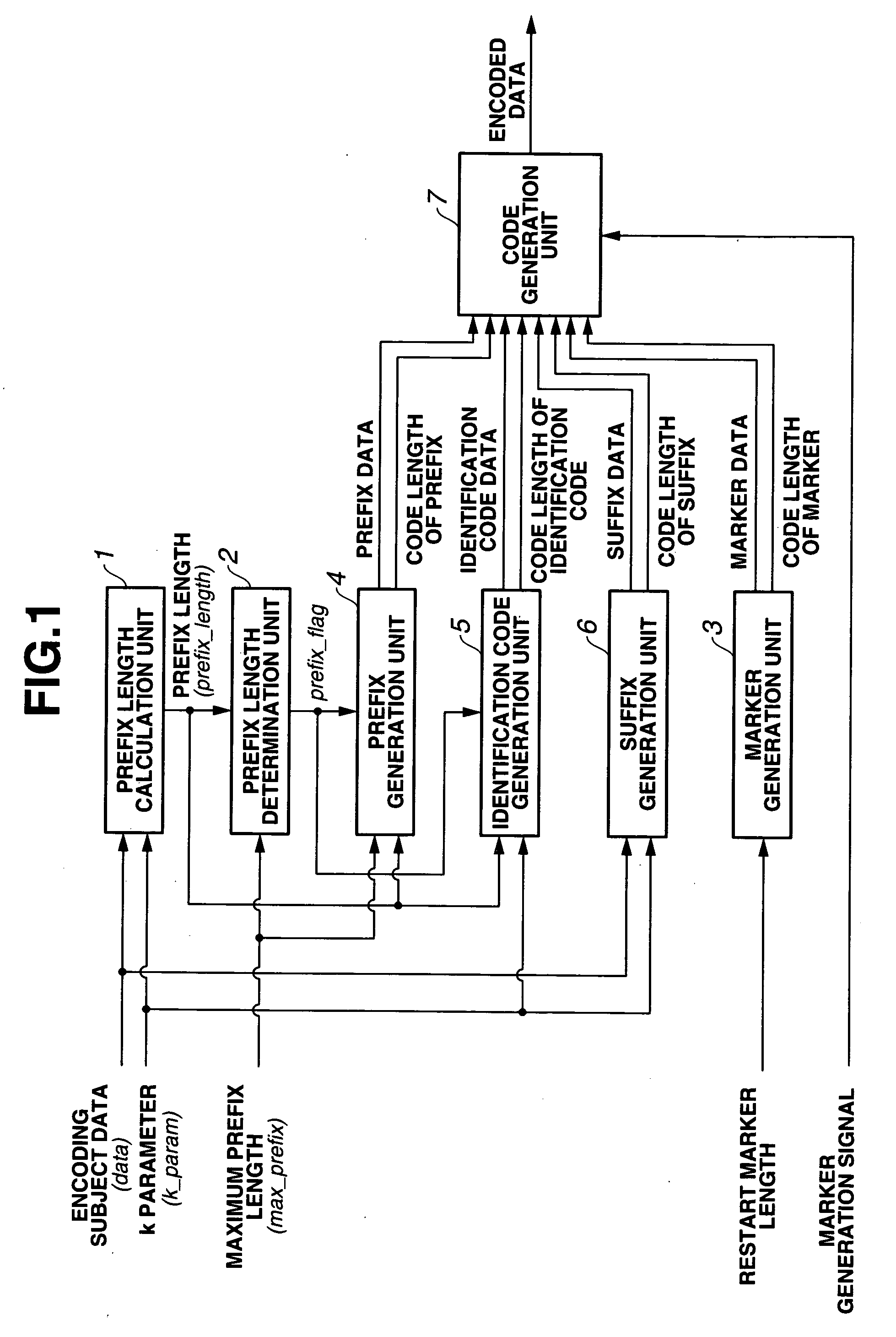
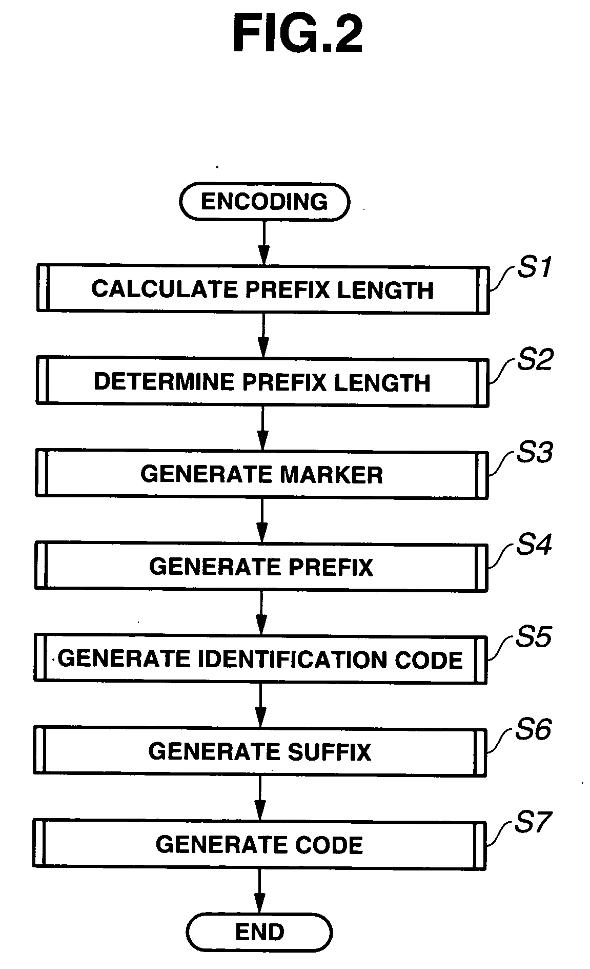
[0034]FIGS. 1 through 12 illustrate a first embodiment of the present invention. FIG. 1 is a block diagram showing the constitution of a data encoding apparatus, FIG. 2 is a flowchart showing encoding processing, FIG. 3 is a flowchart showing prefix length calculation processing, FIG. 4 is a flowchart showing prefix length determination processing, FIG. 5 is a flowchart showing marker generation processing, FIG. 6 is a flowchart showing prefix generation processing, FIG. 7 is a flowchart showing identification code generation processing, FIG. 8 is a flowchart showing suffix generation processing, FIG. 9 is a flowchart showing code generation processing, FIG. 10 is a diagram showing the constitution of a restart marker, FIG. 11 is a diagram showing an example of encoding when the value of upper order bits of encoding subject data is smaller than a maximum prefix length, FIG. 12 is a diagram showing an example of encoding when the value of the upper order bits of the encoding subject ...

second embodiment

[0086]FIGS. 14 through 16 illustrate a second embodiment of the present invention. FIG. 14 is a diagram showing the constitution of a restart marker, FIG. 15 is a flowchart showing marker generation processing, and FIG. 16 is a flowchart showing code generation processing.

[0087] In the second embodiment, identical reference symbols have been allocated to parts which are identical to those of the first embodiment and description thereof has been omitted. The following description focuses on differing parts.

[0088] In the second embodiment, the constitution of the restart marker is slightly altered in order to clarify the end position of the restart marker.

[0089] As shown in FIG. 14, the restart marker used in this embodiment is constituted of 48 bits, the 47 upper order bits being 0 (control code) and the least significant bit being 1 (a code indicating the end of the control code). It is assumed in this embodiment also that the fixed length D of the encoding subject data data is 1...


PUM


Abstract

In a data encoding apparatus, when a prefix length calculation and determination units determine that the code length of a variable length code constituted of continuous bits “0” is equal to or greater than the predetermined maximum prefix length max_prefix during Golomb-Rice encoding of encoding subject data having a fixed length of D bits, second encoding is performed in place of the Golomb-Rice encoding. The second encoding is performed by having a prefix generation unit generate a prefix constituted of continuous bits “0” corresponding to the max_prefix, and having a code generation unit attach the prefix to the upper order bits of the encoding subject data. Furthermore, when a control code such as a restart marker is to be attached, alarmer generation unit generates, as the control code, a code constituted of continuous bits “0” by the number which is equal to or greater than the length of (max_prefix+2×D).

Description

[0001] This application claims benefit of Japanese Application No. 2005-161729 filed in Japan on Jun. 1, 2005, the contents of which are incorporated by this reference. BACKGROUND OF THE INVENTION [0002] 1. Field of the Invention [0003] This invention relates to a data encoding apparatus, a data encoding method, and a recording medium recorded with a program for encoding fixed length encoding subject data. [0004] 2. Description of Related Art [0005] It is generally known that when encoded data are stored at a fixed length and an error occurs during transmission or the like, further data expansion may become impossible. [0006] Hence, international standard encoding methods such as JPEG prescribe a technique of attaching restart markers to the encoded data at appropriate intervals such that even when an error occurs in a part of the data, expansion of the encoded data can be resumed from the position of the subsequent restart marker. An example of this technique is described in Japane...

Claims


Application Information

Patent Timeline
Patent Type & Authority Applications(United States)
IPC IPC(8): H03M7/00
CPCH03M7/40
Inventor ISHIKAWA, TAKASHI
Owner OM DIGITAL SOLUTIONS CORP
Learn More