Millimeter wave electronically scanned antenna

a technology of electronically scanned antennas and which is applied in the direction of antennas, non-resonant long antennas, modular arrays, etc., can solve the problems of high cost, limited scanning performance, and mechanically scanned antennas traditionally used on millimeter wave seeker systems

Active Publication Date: 2006-12-07
LOCKHEED MARTIN CORP
View PDF12 Cites 17 Cited by
  • Summary
  • Abstract
  • Description
  • Claims
  • Application Information

AI Technical Summary

Benefits of technology

[0008] A millimeter wave electronically scanned antenna is disclosed in both passive and in active embodiments. The antenna comprises a plurality of antenna components, wherein an antenna component, includes a coupler; a ground plane; a traveling wave phase shift line electrically connected to the coupler and grounded to the ground plane; and a plurality of fixed phase shifters, each fixed phase shifter electrically connected to the traveling wave phase shift line at a respective point thereon. One such component includes a plurality of radiating elements electromagnetically connected to a respective one of the fixed phase shifters. The antenna further includes a coupling component to which the radiating antenna is coupled to receive control signals and a radio frequency feed.

Problems solved by technology

Mechanically scanned antennas classically used on millimeter wave seeker systems suffer from a variety of problems including high cost, limited scanning performance, and low reliability.
Electronically scanned antennas have greatly improved scanning performance and high reliability, but using traditional techniques have been too costly to implement and suffered from low efficiency (gain).
The multi-bit phase shifting element is responsible for the high cost and low efficiency using the classical design approach.
The associated loss of the typical phase shifting element prohibits the use of the passive electronically scanned antenna in a high performance active missile radar seeker.
Additionally, the classic T / R module approach at Ka band is very demanding due to the tight spacing, low efficiency, high gain / power required to overcome losses, the high transmit / receiver isolation necessary to prevent module oscillation, and the added complexity of multi-bit phase and attenuation control.

Method used


Image

  • Millimeter wave electronically scanned antenna
  • Millimeter wave electronically scanned antenna
  • Millimeter wave electronically scanned antenna

Examples


Embodiment Construction

[0026] Illustrative embodiments of the invention are described below. In the interest of clarity, not all features of an actual implementation are described in this specification. It will of course be appreciated that in the development of any such actual embodiment, numerous implementation-specific decisions must be made to achieve the developers' specific goals, such as compliance with system-related and business-related constraints, which will vary from one implementation to another. Moreover, it will be appreciated that such a development effort, even if complex and time-consuming, would be a routine undertaking for those of ordinary skill in the art having the benefit of this disclosure.

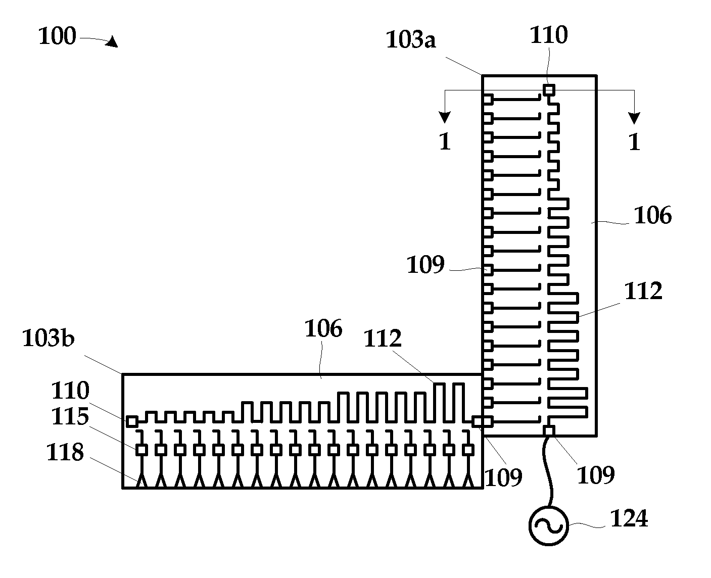
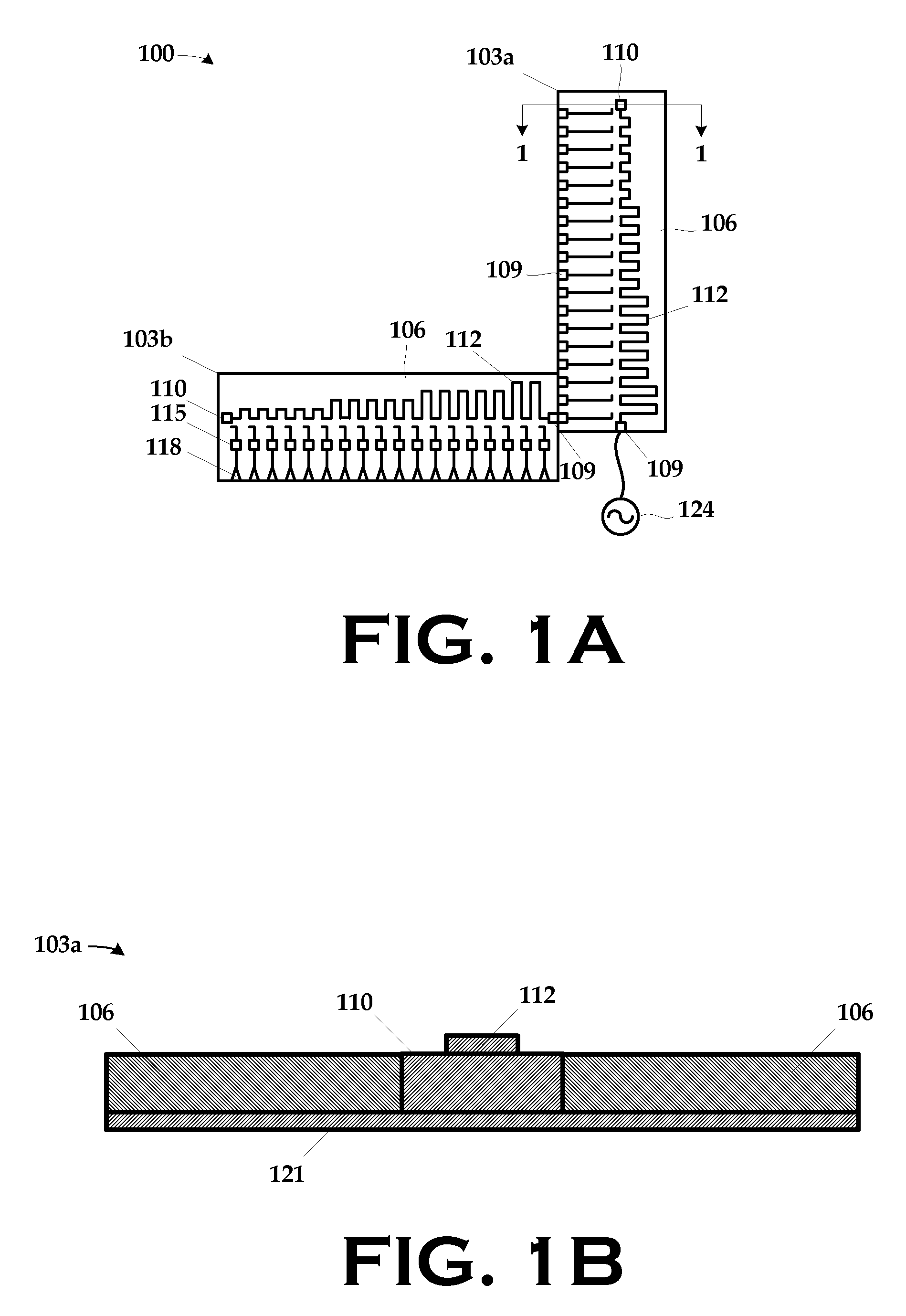
[0027]FIG. 1A illustrates a subassembly 100 comprising two antenna components 103a, 103b in an unassembled view and FIG. 1B is a plan, sectional view of the antenna component 103a along line 1-1 in FIG. 1A. Each of the antenna components 103a, 103b includes a substrate 106. A coupler 109 is for...


PUM


Abstract

A millimeter wave electronically scanned antenna is disclosed in both passive and active implementations. The antenna comprises a plurality of antenna components, wherein an antenna component, includes a coupler; a ground plane; a traveling wave phase shift line electrically connected to the coupler and grounded to the ground plane; and a plurality of fixed phase shifters, each fixed phase shifter electrically connected to the traveling wave phase shift line at a respective point thereon. One such component includes a plurality of radiating elements electromagnetically connected to a respective one of the fixed phase shifters. The antenna further includes a coupling component to which the radiating antenna is coupled to receive control signals and a radio frequency feed.

Description

BACKGROUND OF THE INVENTION [0001] This is a continuation-in-part of co-pending application Ser. No. 11 / 142,982, entitled “Millimeter Wave Passive Electronically Scanned Antenna”, filed Jun. 2, 2005, in the name of the inventor Cole A. Chandler and commonly assigned herewith. This application is hereby incorporated by reference as if expressly set forth herein verbatim. [0002] 1. Field of the Invention [0003] The present invention is directed to millimeter wave antennas, and, more particularly, to a millimeter wave electronically scanned antenna. [0004] 2. Description of the Related Art [0005] Mechanically scanned antennas classically used on millimeter wave seeker systems suffer from a variety of problems including high cost, limited scanning performance, and low reliability. Electronically scanned antennas have greatly improved scanning performance and high reliability, but using traditional techniques have been too costly to implement and suffered from low efficiency (gain). Trad...

Claims


Application Information

Patent Timeline
Patent Type & Authority Applications(United States)
IPC IPC(8): H01Q19/06
CPCH01Q3/22H01Q21/0075H01Q21/0025H01Q3/38
Inventor CHANDLER, COLEA
Owner LOCKHEED MARTIN CORP
Why Eureka
Try Eureka