Electro-optical device and electronic apparatus

a technology of optical devices and electronic devices, applied in non-linear optics, instruments, optics, etc., can solve the problems of reducing the aperture ratio of the transmissive display, the complexity of the manufacture process, and the simultaneous decrease of the substantial aperture ratio of the reflective display, so as to achieve the effect of not reducing the saturation of the colored region, reducing the area of the light reflecting region, and improving the brightness of the reflective display

Inactive Publication Date: 2006-12-07
JAPAN DISPLAY WEST
View PDF7 Cites 12 Cited by
  • Summary
  • Abstract
  • Description
  • Claims
  • Application Information

AI Technical Summary

Benefits of technology

[0039] Preferably, in at least one of the light reflecting regions of the three sub-pixels corresponding to the three colors, a portion is provided in which the colored layer is not provided. According to this configuration, the portion where the colored layer is not formed is provided in the at least one of the three kinds of light reflecting regions where the colored layers are disposed, and the bright of the reflective display can be further improved. Even though the saturation of the colored region is not lowered or the area of the light reflecting region is not increased, the brightness of the reflective display can be sufficiently ensured, and thus the improvement of the saturation of the colored layer or the increase in the area of the light transmitting region can be implemented, which results in improving the quality of the transmissive display.
[0040] Preferably, the colored regions corresponding to the three colors are among a visible light region where hues vary in accordance with a wavelength, a colored region of a blue color, a colored region of a red color, and one of colored regions of two kinds of different colors selected from hues from blue to yellow, and the colored region corresponding to the color other than the three colors is the other of the colored regions of two kinds of different hues selected from hues from blue to yellow. By adding one color other than the three colors, the color reproducibility of the color display can be further improved. In this case, in addition to broadening the color reproducibility range, it is effective that the colored regions of the two kinds of hues which are selected from hues from the blue to the yellow are respectively a colored region of hues from blue to green and a colored region from green to orange.
[0041] Preferably, the colored regions corresponding to the three colors are a first colored region in which a peak of a wavelength of light transmitted through the colored region is within a range of 415 to 500 nm, a second colored region in which a peak of a wavelength of light transmitted through the colored region is 600 nm or more, and one of a third colored region in which a peak of a wavelength of light transmitted through the colored region is within a range of 485 to 535 and a fourth colored region in which a peak of a wavelength of light transmitted through the colored region is within a range of 500 to 590, and the colored region corresponding to the colors other than the three colors is the other of the third colored region and the fourth colored region. By adding a new color other than the three colors, the color reproducibility of the color display can be further improved. In this case, in addition to the broadening the color reproducibility range, it is effective that the third colored region is a colored region in which a peak of a wavelength of light transmitted through the colored region is within a range of 495 to 520 nm, and the fourth colored region is a colored region in which a peak of a wavelength of light transmitted through the colored region is within a range of 510 to 585 nm.
[0042] According to a sixth aspect of the invention, an electronic apparatus includes the above-described electro-optical device, and a control unit which controls the electro-optical device. According to this configuration, the electro-optical device can achieve the transmissive display and the reflective display, and can have high responsibility with respect to the variation of the external environment. Accordingly, when the electro-optical device is mounted in a cellular phone, a significant effect can be obtained.

Problems solved by technology

In order to have colored layers with different saturations from each other in the transmitting and reflecting regions, an amount of colorants contained in the colored layer should be changed, such that the different kinds of the colored layers cause a manufacture process thereof to be complicated.
However, in the electro-optical device which allows both the transmissive display and the reflective display to be utilized, a substantial aperture ratio of the transmissive display decreases due to the formation of the reflecting region while a substantial aperture ratio of the reflective display simultaneously decreases due to the formation of the transmitting region, such that it is difficult to secure display brightness and utilize a visual balance between both reflective display and transmissive display.
However, when the colored layers of the reflecting and transmitting regions are formed of different materials to perform high quality transmissive display, the number of process steps of manufacturing the color filter increases, which causes an increase in manufacturing cost.

Method used


Image

  • Electro-optical device and electronic apparatus
  • Electro-optical device and electronic apparatus
  • Electro-optical device and electronic apparatus

Examples


first embodiment

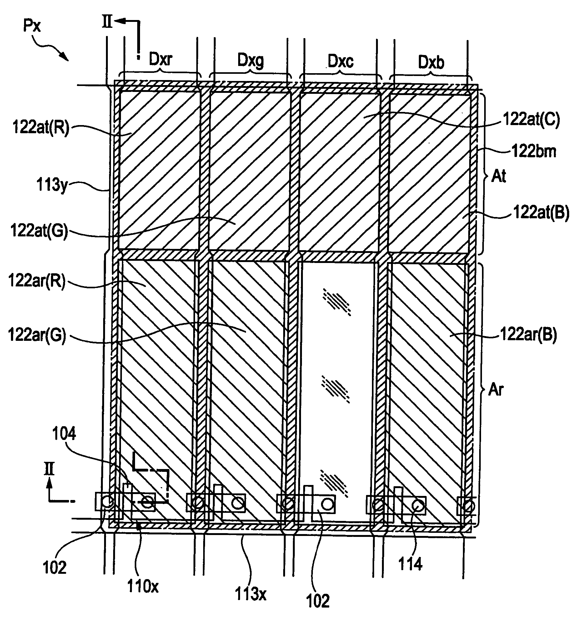
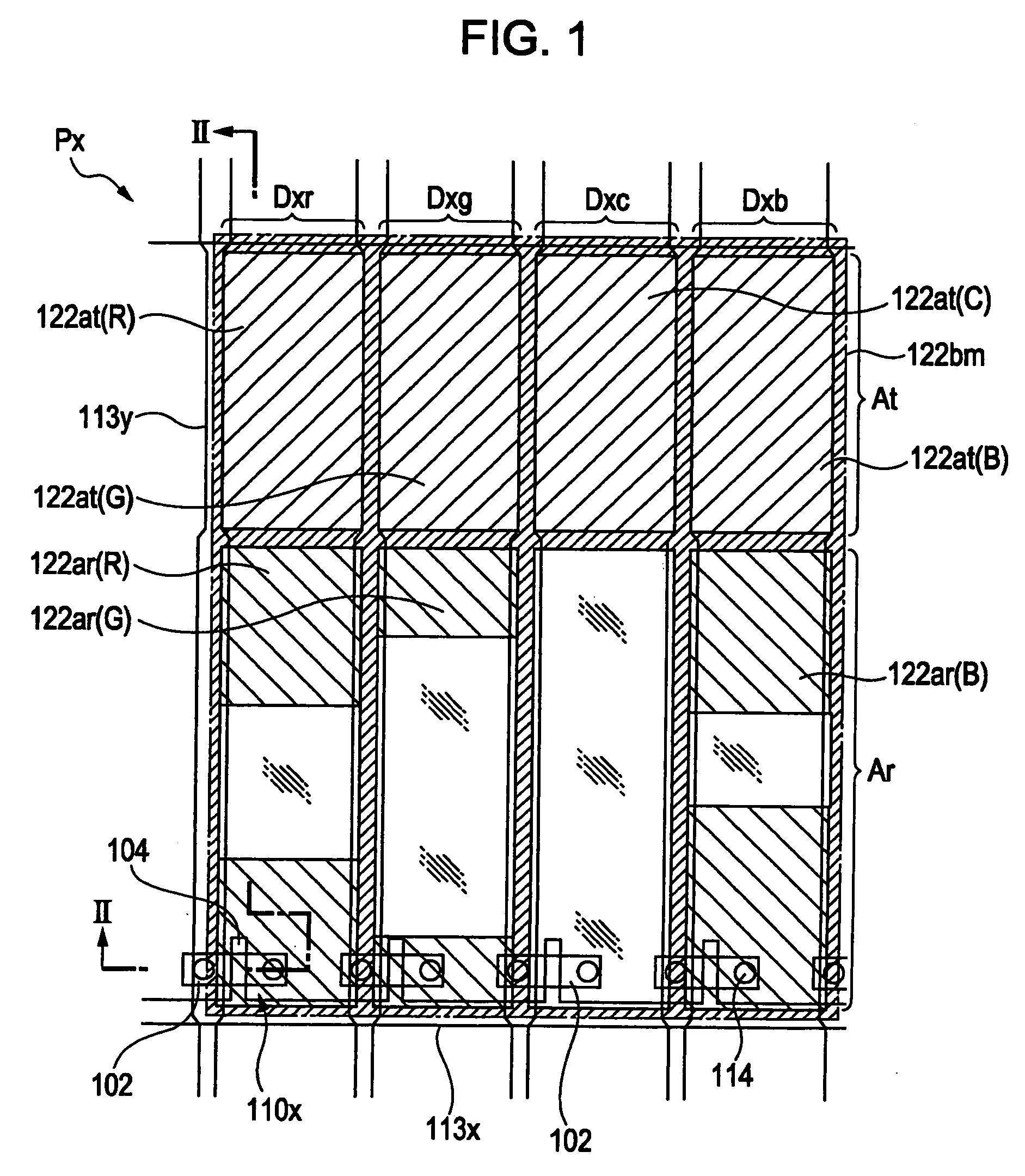
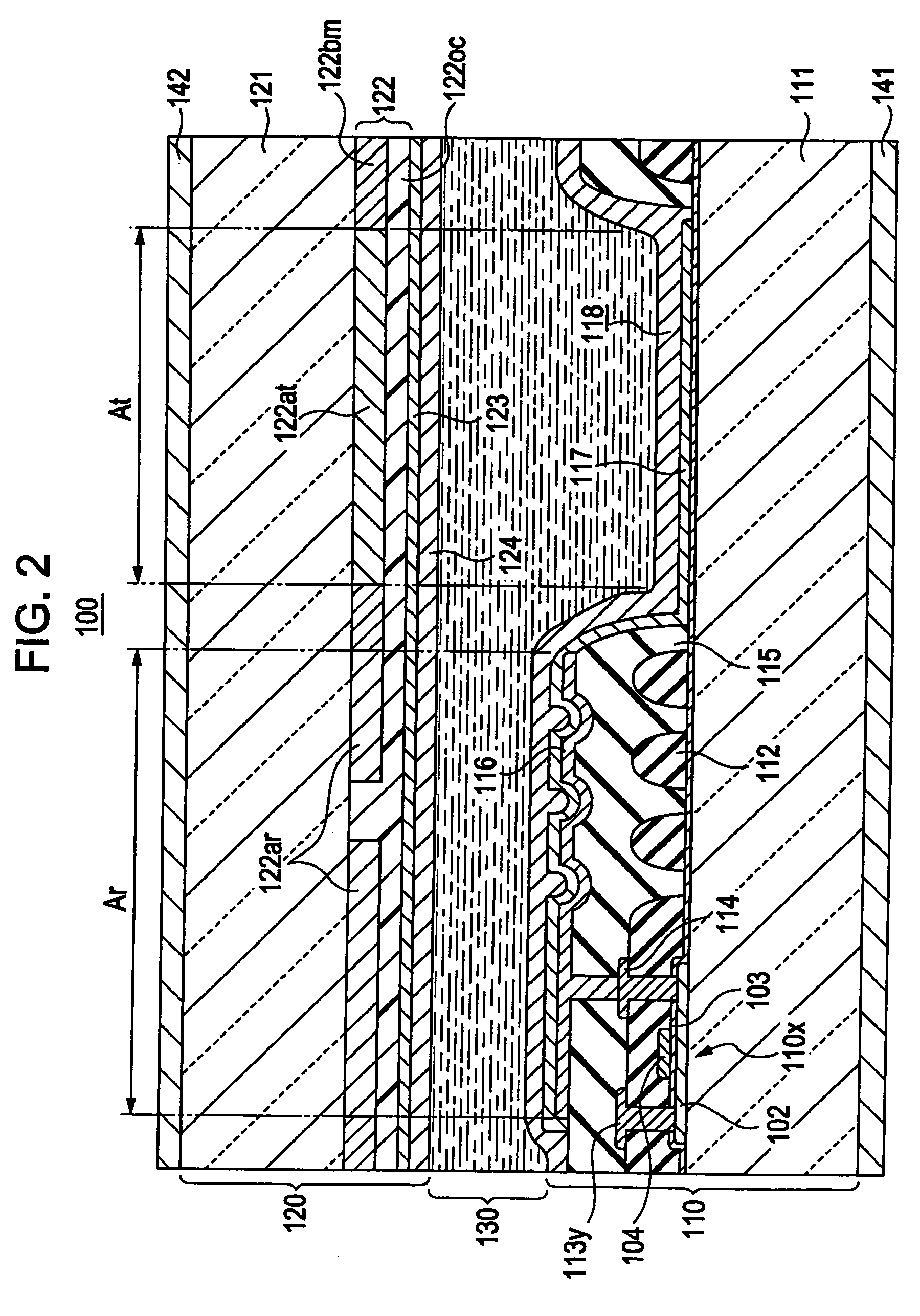
[0052] Hereinafter, preferred embodiments of the invention will be described in detail with reference to the accompanying drawings. FIG. 1 is an enlarged perspective plan view illustrating an internal structure of a display unit (pixel) of the pixel arrangement in an electro-optical device according to the first embodiment of the invention. FIG. 2 is an enlarged longitudinal cross-sectional view illustrating a sectional structure of one pixel in the same electro-optical device.

[0053] This embodiment illustrates a liquid crystal device that is a kind of the electro-optical device. As shown in FIG. 2, a base 110 and a base 120 are bonded to each other through a sealant (not shown) at a predetermined gap, and a liquid crystal layer 130 is disposed between the base 110 and the base 120.

[0054] The base 110 includes a transparent substrate 111 that is made of glass or plastic. A TFT (switching element) 110X is formed on an inner surface of the substrate 111. The TFT 110X includes a semi...

second embodiment

[0096] Next, another embodiment of the invention will be described with reference to FIG. 3. FIG. 3 is a schematic plan view of a structure of a pixel according to the second embodiment of the invention. In this embodiment, the same numerals are denoted in the same portions as the first embodiment, such that descriptions thereof will be omitted.

[0097] In this embodiment, in one pixel Px, the sub-pixels Dxr, Dxc, and DxB are provided. In each of the three kinds of sub-pixels, similar to the first embodiment, the light transmitting region At and the light reflecting region Ar are provided, and the colored layers 122at and 122ar of red (R), cyan (C), and blue (B) are provided in each region.

[0098] In the meantime, in another sub-pixel Dxg′, the light transmitting region At and the light reflecting region Ar are provided, and the colored layer 122at of green (G) is disposed in the light transmitting region At. However, the colored layer is not disposed in the light reflecting region A...

third embodiment

[0101]FIG. 4 is a schematic plan view of a structure of one pixel of an electro-optical device in accordance with another embodiment of the invention. In the third embodiment, the same numerals are also denoted in the same portions as any of the above-described embodiments, such that descriptions thereof will be omitted. This embodiment is the same as the above-described embodiments in that the colored layer is not disposed in the light reflecting region Ar of the sub-pixel Dxc. However, this embodiment is different from the above-described embodiment in that in the light reflecting region Ar that is provided in the sub-pixels Dxr, Dxg, and Dxb, the colored layers 122ar of red (R), green (G), and blue (B) are entirely formed.

[0102] As described above, the colored region is disposed in the light reflecting region Ar of the sub-pixel Dxc, and the brightness of the reflective display can be easily obtained. Therefore, it is not substantially necessary that the portion where the colore...


PUM

PropertyMeasurementUnit
wavelengthaaaaaaaaaa

Abstract

An electro-optical device includes a plurality of sub-pixels each of which has a light transmitting region and a light reflecting region, colored layers being disposed so as to correspond to the plurality of sub-pixels, the colored layers having filter colors of a three primary color system and a filter color of a complementary color system other than the three-primary-color system, transmissive display being performed in the light transmitting region, reflective display being performed in the light reflecting region, and color display being performed in both reflective display and transmissive display. Further, in each of the plurality of sub-pixels, a colored layer of any one of the filter colors of the three primary color system and the filter color of the complementary color system other than the three primary color system is disposed in at least the light transmitting region, and the colored layer is not provided in the light reflective region of the sub-pixel in which the colored layer of the filter color of the complementary color system is disposed.

Description

[0001] This application claims the benefit of Japanese Patent Application No. 2005-146426, filed May 19, 2005, and Japanese Patent Application No. 2005-303255, filed Oct. 18, 2005. The entire disclosures of the prior applications are hereby incorporated by reference herein in their entirety. BACKGROUND [0002] 1. Technical Field [0003] The invention relates to an electro-optical device and an electronic apparatus, and more particularly, to an electro-optical device which includes a color filter having a plurality of colored layers and allows both reflective display and transmissive display of colors to be implemented by the color filter. [0004] 2. Related Art [0005] In general, a color filter is provided for allowing color display to be performed in a liquid crystal display (LCD) or other various electro-optical devices. This color filter is, for example, formed such that a plurality of, different colored layers, such as, red, green, and blue colored layers, are respectively disposed...

Claims


Application Information

Patent Timeline
Patent Type & Authority Applications(United States)
IPC IPC(8): G02F1/1335
CPCG02F1/133514G02F2201/52G02F2001/134345G02F1/133555G02F1/134345G02F1/1335
Inventor TAKIZAWA, KEIJI
Owner JAPAN DISPLAY WEST
Why Eureka
Try Eureka