Variable shape lens

Active Publication Date: 2006-12-07
KONINKLIJKE PHILIPS ELECTRONICS NV
View PDF7 Cites 18 Cited by
  • Summary
  • Abstract
  • Description
  • Claims
  • Application Information

AI Technical Summary

Benefits of technology

[0013] The meniscus between the two fluids acts as a lens, and so the effective shape of the lens can easily be adjusted by changing the shape of the meniscus. As no mechanical components are required within the optical path of the lens, then the optical path does not suffer from mechanical wear and tear. Further, the lens

Problems solved by technology

Due to the movement of the membrane surface, it is difficult to maintain good optical properties and it is susceptible to vibrations.
Further, it is susceptible to mechanical fatigue.
Consequently, obtaining a range of desired lens shapes can be problematic, particularly if the elasticity of the membrane 42 changes over time.
Additionally, flexible membranes are not normally gas tight, result

Method used


Image

  • Variable shape lens
  • Variable shape lens
  • Variable shape lens

Examples


Example

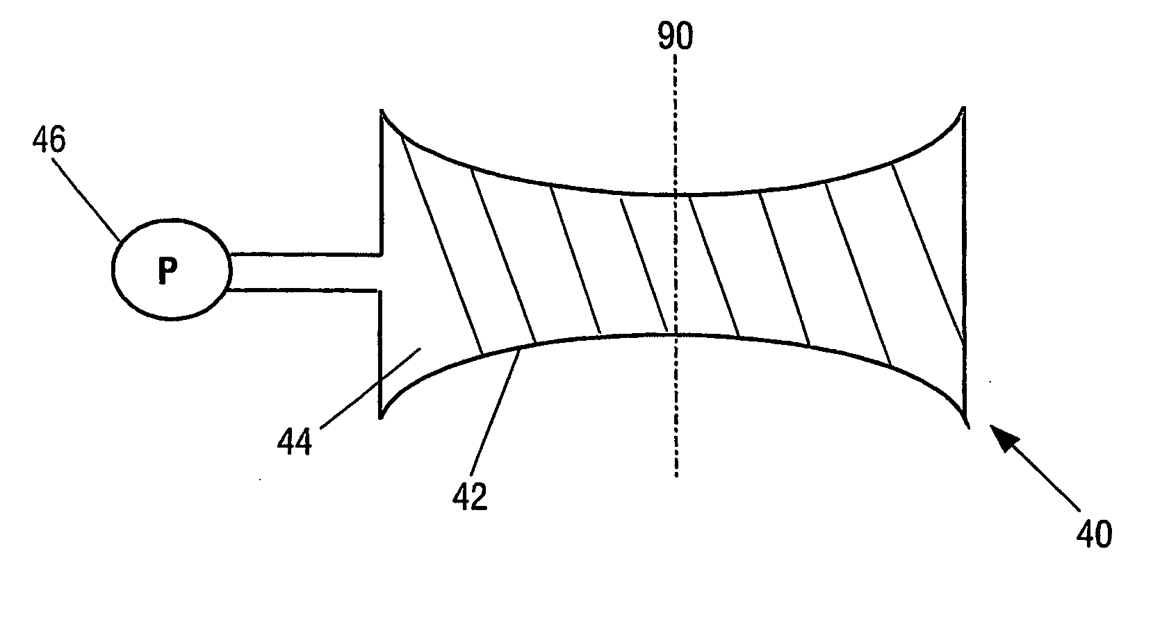
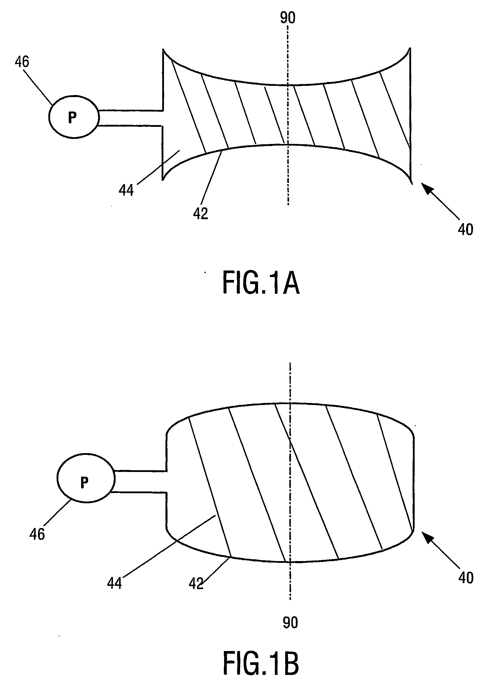
[0028]FIG. 3A shows a variable lens in accordance with a first embodiment of the present invention. The lens 100 can be regarded as being formed of two distinct elements: a lens function formed by the meniscus 150 between two fluids 130, 140, and a pump 110 arranged to alter the shape of the lens function.

[0029] A fluid is a substance that alters its shape in response to any force, that tends to flow or to conform to the outline of its chamber, and that includes gases, liquids, vapours, and mixtures of solids and liquids capable of flow.

[0030] The two fluids 130, 140 are substantially immiscible i.e. the two fluids do not mix. The two fluids 130, 140 have different refractive indices. A lens function is thus provided by the meniscus 150 formed along the contact area of the two fluids, as the fluids have different refractive indices. A lens function is the ability of the meniscus 150 to focus (converge or diverge) one or more wavelengths of the light. In this particular embodiment,...


PUM


Abstract

A variable lens (100; 200; 220; 240; 250; 300; 350) comprises a chamber (125), with an optical axis (90) extending through the chamber (125). The chamber (125) contains a first fluid (130) and a second fluid (140) in contact over a meniscus (150)>extending transverse the optical axis (90). The perimeter of the meniscus (150) is fixedly located on an internal surface (120) of the chamber (125). The fluids (130, 140) are substantially immiscible and have different indices of refraction. A pump (110) is arranged to controllably alter the shape of the meniscus (150) by altering the relative volume of each of the fluids (130, 140) contained within the chamber (125).

Description

FIELD OF THE INVENTION [0001] The present invention relates to a variable lens, to optical devices including such a lens, and to methods of manufacturing such lenses and such devices. BACKGROUND OF THE INVENTION [0002] A lens is a device that can focus (converge or diverge) one or more wavelengths of light. The term light is understood to include both visible electromagnetic radiation, and other wavelengths of electromagnetic radiation. [0003] A variable (or adjustable) lens is a lens in which one or more properties of the lens can be controllably adjusted e.g. in which either the focal length or the position of the lens can be altered. [0004] DE 19710668 describes a variable lens system 40, as illustrated in FIGS. 1A and 1B. The lens system 40 comprises a resilient membrane 42 filled with a fluid 44. The pressure of the fluid 44 within the membrane is controlled by means of a pump 46. The dotted line illustrates the optical axis 90 of the lens system 40. The membrane 42 acts as a v...

Claims


Application Information

Patent Timeline
IPC IPC(8): G02B3/12G02B3/14G02B26/02G11B7/00G11B7/135
CPCG02B3/14G02B26/005G11B7/1374G11B2007/13727G11B7/13925G11B2007/0006G11B2007/0013G11B7/1376G02B3/12
Inventor KUIPER, STEINHENDRIKS, BERNARDUS H.W.
Owner KONINKLIJKE PHILIPS ELECTRONICS NV
Why Eureka
Try Eureka