
Three-mode continuously variable transmission with a direct low mode and two split path high modes

a continuously variable transmission and low mode technology, applied in the direction of belts/chains/gears, mechanical equipment, belts/chains/gears, etc., can solve the problems of reducing the transmission output torque, reducing the overall efficiency of the transmission during vehicle launch, and recirculating a large portion of power, so as to improve the overall efficiency of the transmission and the three-mode continuously variable technology

Active Publication Date: 2006-12-07
GM GLOBAL TECH OPERATIONS LLC
View PDF13 Cites 23 Cited by
  • Summary
  • Abstract
  • Description
  • Claims
  • Application Information

AI Technical Summary

Benefits of technology

[0004] It is an object of the present invention to provide an improved three-mode continuously variable transmission.

Problems solved by technology

While these types of transmissions provide a simplified control system for forward and reverse, they do have the disadvantage in that a high portion of the power is recirculated through the continuously variable unit and the gearing during the vehicle launch operation.
This reduces the transmission output torque, tractive effort, and the overall efficiency of the transmission during vehicle launch.

Method used


Image

  • Three-mode continuously variable transmission with a direct low mode and two split path high modes
  • Three-mode continuously variable transmission with a direct low mode and two split path high modes
  • Three-mode continuously variable transmission with a direct low mode and two split path high modes

Examples


Embodiment Construction

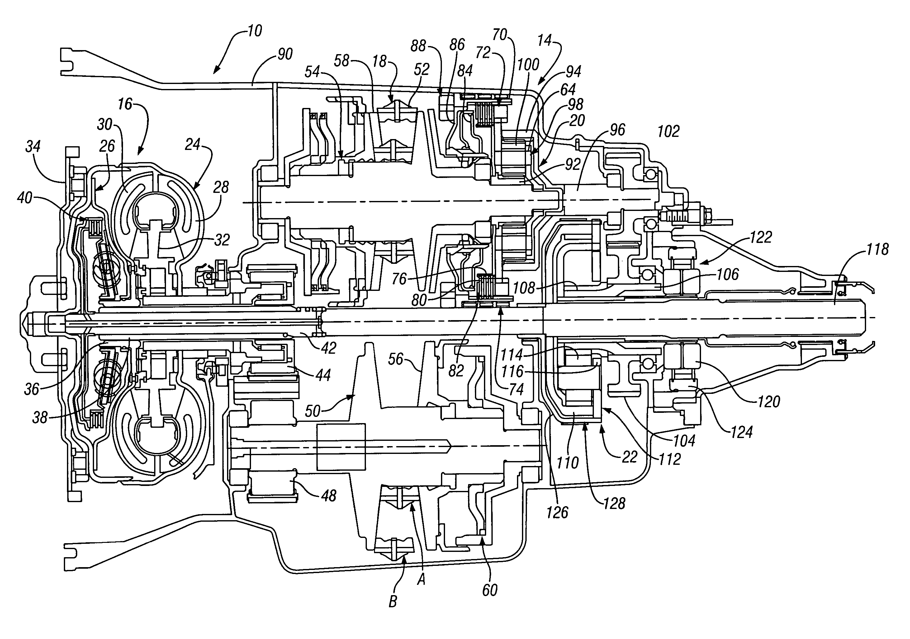
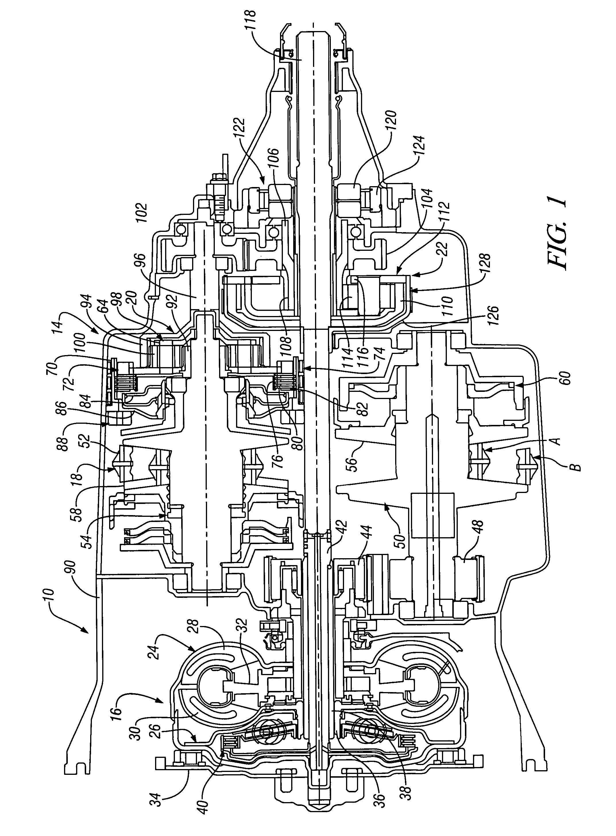
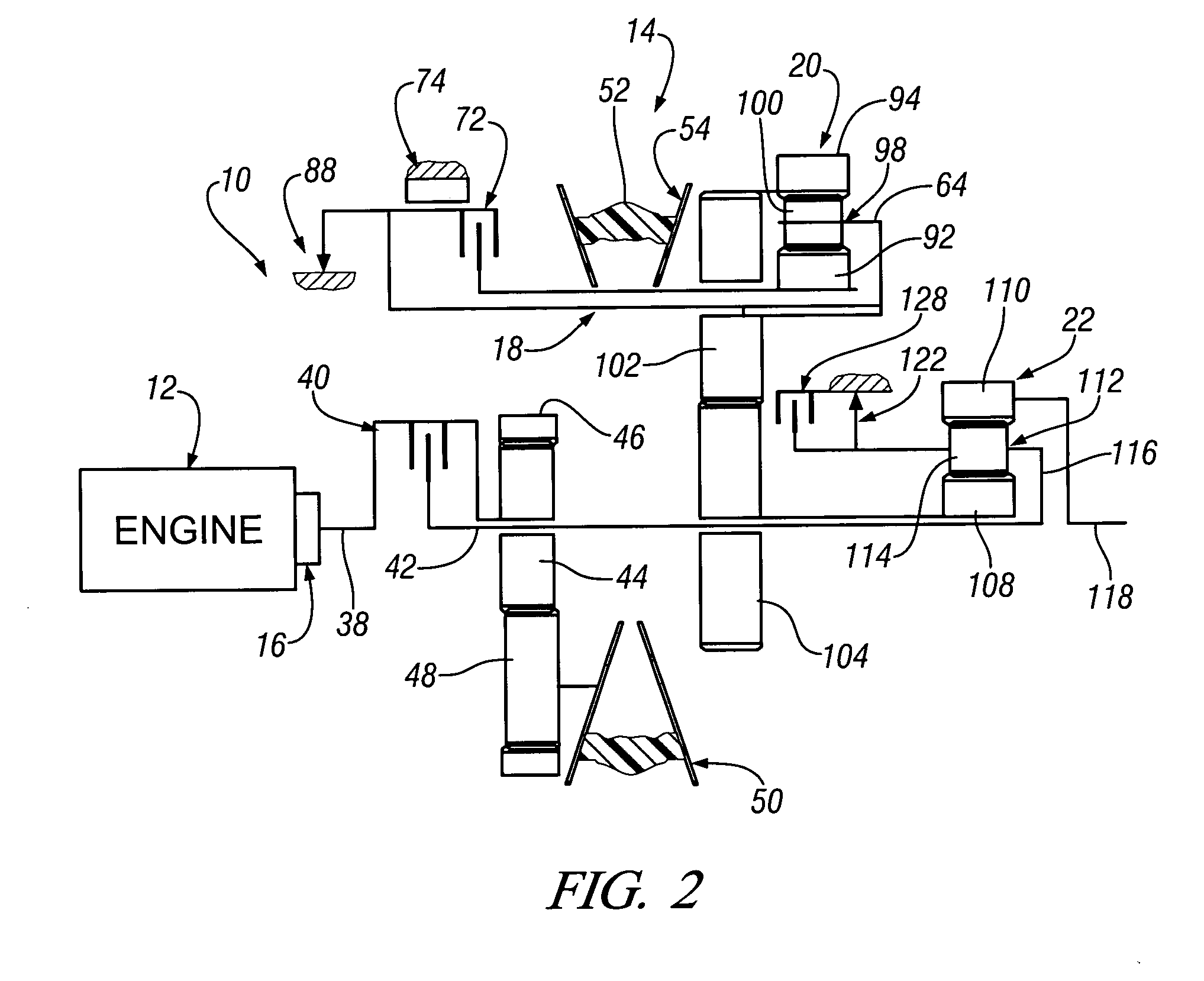
[0014] Referring to the drawings, wherein like characters represent the same or corresponding parts throughout the several views, there is seen in FIGS. 1 and 2 a powertrain 10 having an engine or other conventional mechanical power source 12, and a continuously variable ratio transmission (CVT) 14. The CVT 14 includes a starting device or mechanism 16, a continuously variable unit (CVU) 18, a first planetary gearset or arrangement 20, and a second planetary gearset or arrangement 22.

[0015] The starting device 16 is shown as a conventional torque converter 24 and torque converter clutch 26. The torque converter 24 includes an impeller 28, a turbine 30, and a stator 32. The impeller 28 is continuously connected with the engine 12 through a flex plate 34. The turbine 30 and torque converter clutch 26 are drivingly connected through a hub 36 with an input shaft 38. Also disposed between the torque converter 24 and the flex plate 34 is a selectively engageable torque transmitting mecha...


PUM


Abstract

A powertrain includes a continuously variable transmission having a starting mechanism, a continuously variable unit (CVU), and a pair of planetary gear arrangements. The continuously variable transmission also includes a plurality of torque transmitting mechanisms which are selectively engageable in combinations of two to establish a reverse mode of operation between the starting mechanism and a transmission output shaft, a low direct mode of operation, an intermediate split mode of operation, and a high split mode of operation.

Description

TECHNICAL FIELD [0001] This invention relates to power transmissions and, more particularly, to continuously variable power transmissions having a continuously variable unit disposed to operate with a planetary gear arrangement. BACKGROUND OF THE INVENTION [0002] Passenger vehicles in today's market incorporate a power transmission that has at least three forward ratios, and quite often, six forward ratios. These power transmissions are utilized to extend the operating range of the vehicle engine by reusing the engine speed range as the gear ratio is changed. In order to make more efficient use of the engine and its speed range, it has been proposed to employ a continuously variable type transmission wherein the ratio change within the transmission is continuous over during a drive range during which the engine speed might be held constant. For example, the continuously variable transmission ratios are changed from an underdrive of four to one (4:1) to an overdrive of point four to ...

Claims


Application Information

Patent Timeline
Patent Type & Authority Applications(United States)
IPC IPC(8): F16H37/02
CPCF16H2037/088F16H37/0846
Inventor COFFEY, DANSEFCIK, MICHAEL C.
Owner GM GLOBAL TECH OPERATIONS LLC
Learn More