Multi-lumen catheter with attachable hub

a multi-lumen catheter and hub technology, applied in the field of medical instruments, can solve the problems of poor dialysis treatment effect, lack of accuracy of catheter tip placement, and lack of double-lumen catheters

Inactive Publication Date: 2006-12-07
TELEFLEX LIFE SCI LTD
View PDF24 Cites 53 Cited by
  • Summary
  • Abstract
  • Description
  • Claims
  • Application Information

AI Technical Summary

Benefits of technology

[0006] The present invention is a double lumen catheter with a selectively detachable hub assembly that allows the catheter tip to be positioned accurately within a patient's vein prior to subcutaneous tunneling. The distal end of the catheter tube is not permanently attached to the hub assembly. Therefore, the catheter may be reverse tunneled after the tips have been positioned.
[0007] The hub assembly includes at least two cannulae that coordinate and correspond to the at least two lumen at the distal end of the catheter tube. Once the hub assembly is connected to the catheter tube so as to provide fluid communication therebetween, preferably, a connection cover and a malleable compression sleeve are secured into place. Preferably, the connection cover is threaded to mate with a threaded connection on the hub assembly. The connection cover and the compression sleeve together create force to prevent inadvertent separation of the catheter tube from the hub assembly while maintaining the diameter of the lumens throughout the connection area.

Problems solved by technology

Both types, however, present certain deficiencies.
While double lumen catheters (e.g., U.S. Pat. No. 4,895,561) allow for a single venous insertion of the catheter into the desired vein, double lumen catheters typically do not provide for accuracy of catheter tip placement.
Non-optimal tip position may significantly lower flow values, resulting in less effective dialysis treatment.
The initial estimate and subsequent forward tunneling may result in less than optimal tip placement.
Deficiencies, however, exist in this method of catheterization as well.
One problem associated with this method is that this method requires two separate venous insertions, namely, two tunnels and two of each accessory instrument used for the procedure.

Method used


Image

  • Multi-lumen catheter with attachable hub
  • Multi-lumen catheter with attachable hub
  • Multi-lumen catheter with attachable hub

Examples


Embodiment Construction

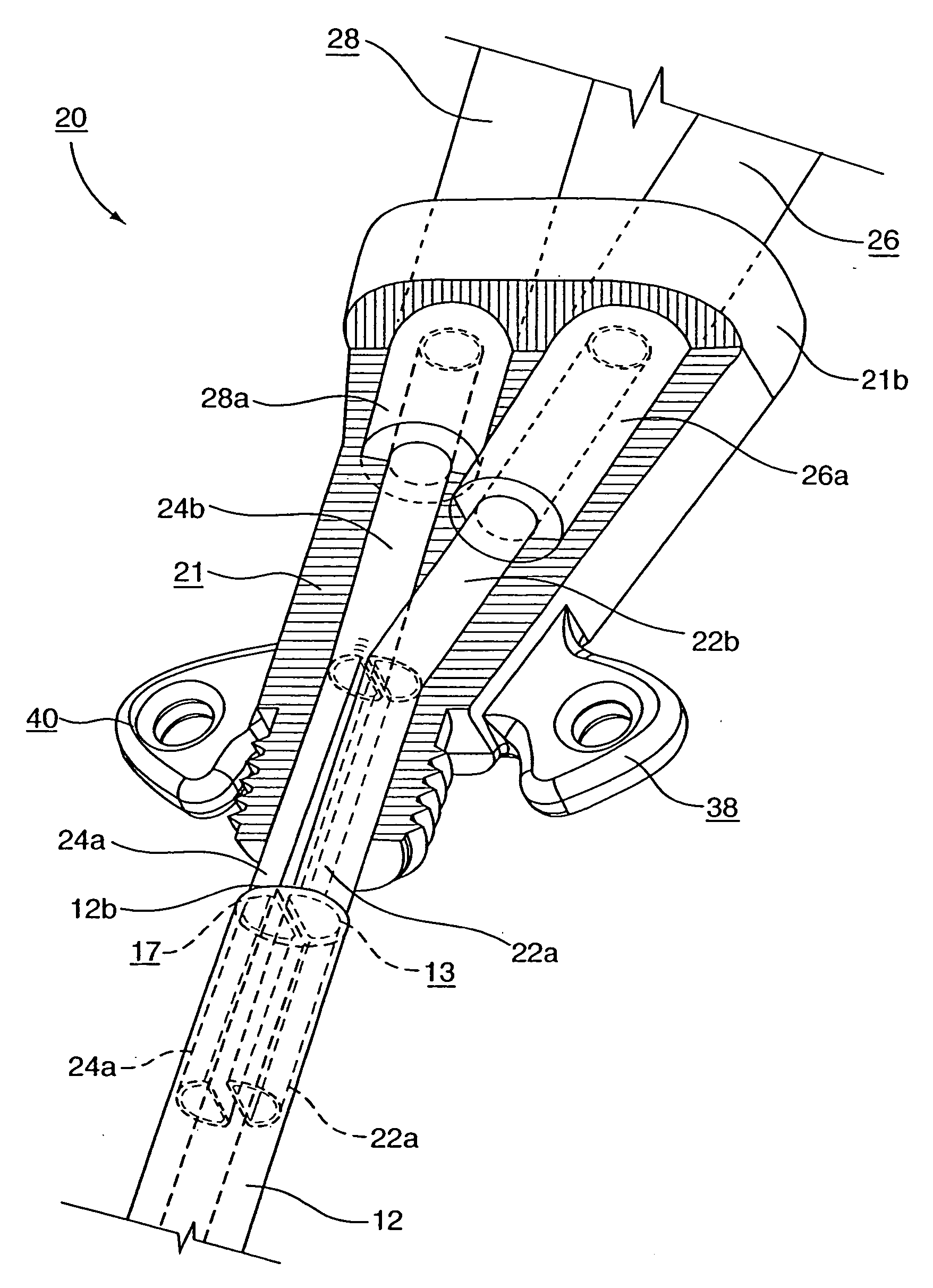
[0017] For the purposes of the following description and the claims appended hereto, the relative term “proximal” refers to those portions of a catheter and those portions of components of the catheter which are nearest the insertion end of the catheter, that is, the end of the catheter that as it is inserted into an area of a patient's body being catheterized, such as a blood vessel. Conversely, the relative term “distal” refers to those portions of a catheter and those portions of components of the catheter which are farthest from the insertion end of the catheter.

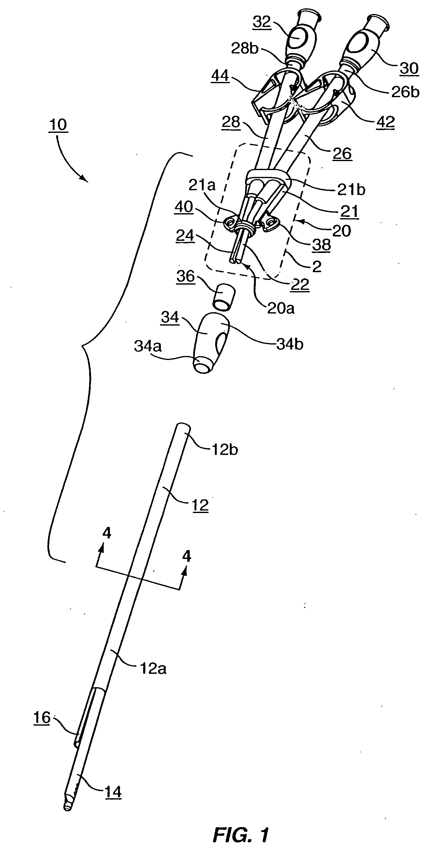
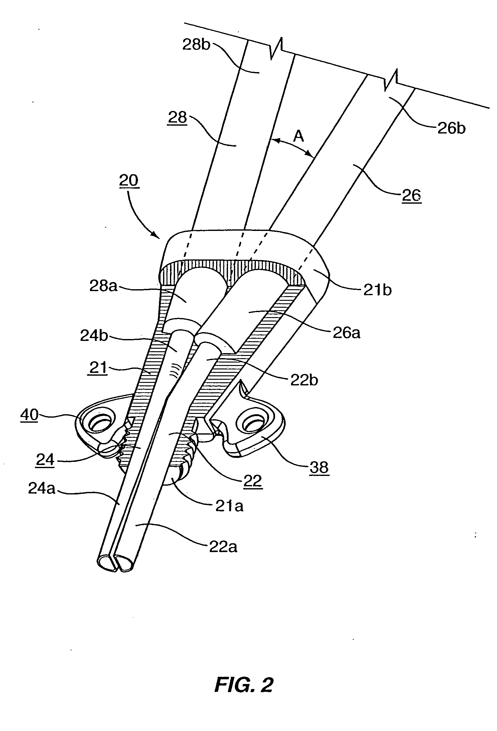
[0018] As shown in the Figures, the present invention is a multi-lumen catheter assembly 10 having a selectively attachable hub assembly 20. As shown in FIG. 1, a multi-lumen catheter tube 12 is formed with a proximal portion 12a and a distal portion 12b. The distal portion 12b of the catheter tube 12 is selectively attachable to the proximal portion 20a of the hub assembly 20. In this manner, the hub assembly 20 may be...


PUM


Abstract

The present invention is a multi-lumen catheter assembly having a selectively attachable hub including a multi-lumen catheter tube that has a proximal portion and a distal portion and a hub assembly that has a proximal portion and a distal portion, whereby the distal portion of the catheter tube is selectively attachable to the proximal portion of the hub assembly after subcutaneous insertion of the proximal portion of the catheter tube into a patient.

Description

RELATED APPLICATIONS [0001] This is a continuation-in-part of pending U.S. patent application Ser. No. 10 / 086,033, filed Feb. 28, 2002, which is a continuation of application Ser. No. 09 / 769,052 filed Jan. 24, 2001.FIELD OF THE INVENTION [0002] The present invention relates generally to medical instrumentation and more specifically to a multi-lumen catheter with a selectively attachable hub assembly that allows the catheter tip to be positioned accurately prior to subcutaneous reverse tunneling. BACKGROUND OF THE INVENTION [0003] Catheters, generally, are hollow, flexible tubes for insertion into a body cavity, duct, or vessel to allow the passage of fluids or distend a passageway. Catheters are often used for temporary or long-term dialysis treatment. Dialysis treatment provides for blood to be withdrawn from the patient, purified, and then returned to the patient. Thus, in dialysis treatment, catheters are used to allow passage of a patient's blood into and out of the patient's bo...

Claims


Application Information

Patent Timeline
Patent Type & Authority Applications(United States)
IPC IPC(8): A61M25/00
CPCA61M25/0028A61M2025/0037A61M2025/0031A61M25/0097
Inventor WILSON, JON S.FLEMING, CARL M.CASSIDY, KENNETH T.BOYD, RONALD D.FLEMING, GARY S.
Owner TELEFLEX LIFE SCI LTD
Why Eureka
Try Eureka