
Target wheel pre-assembly for a camshaft phaser

Inactive Publication Date: 2006-12-14
DELPHI TECH INC
View PDF5 Cites 14 Cited by
  • Summary
  • Abstract
  • Description
  • Claims
  • Application Information

AI Technical Summary

Benefits of technology

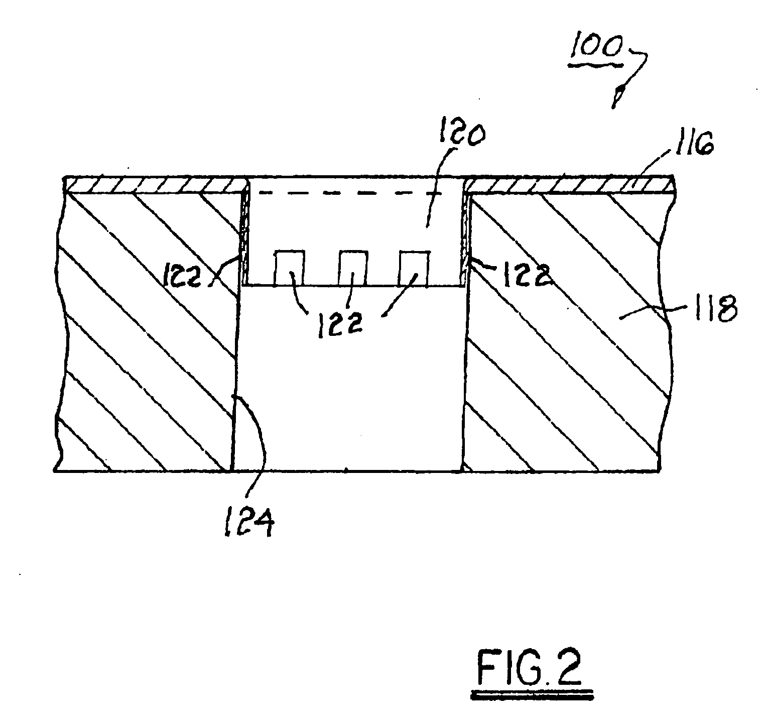
[0005] Briefly described, a camshaft phaser rotor includes a central bore for passage of a mounting bolt during attachment of an assembled camshaft phaser to an end of a camshaft. A target wheel barbed axial extension is entered into the bore, or into a counter bore disposed coaxially to the central bore, to fix the target

Problems solved by technology

However, it has been found that the tolerance stackup of the components is such that indexing by this method is insufficiently precise for maximizing engine control.

Method used


Image

  • Target wheel pre-assembly for a camshaft phaser
  • Target wheel pre-assembly for a camshaft phaser
  • Target wheel pre-assembly for a camshaft phaser

Examples


first embodiment

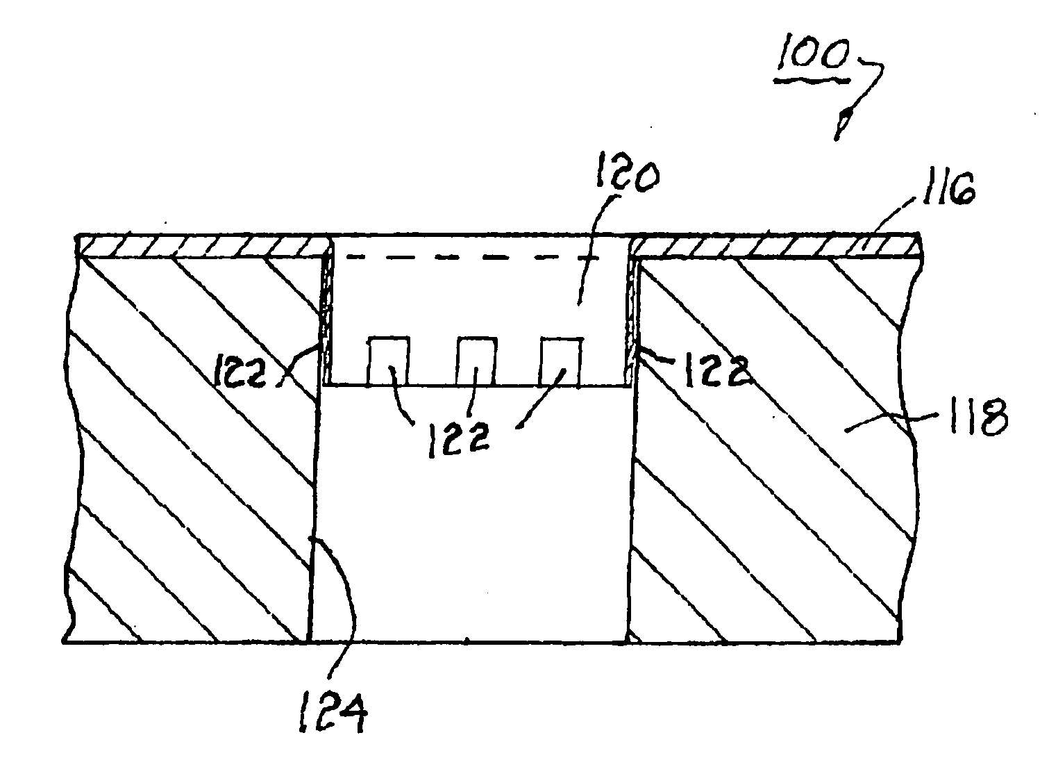
[0016] Referring to FIG. 2a, a variation of the first embodiment, in accordance with the invention, is shown. In a pre-assembly 100′, target wheel 116′ is provided with upper flange 117 and tubular axial extension 120′. Wheel 116 is also provided with flange end 119 disposed distally from flange 117. Extension 120′ comprises a plurality of barbs 122 formed by stamping. Rotor 118′ includes bore 123 for receiving the mounting bolt, co-axial rotor counter bore 124′, and ledge 125 disposed between the bores.

[0017] In a manufacturing step ahead of the final assembly of a camshaft phaser, wheel 116′ is assembled to rotor by a) angularly indexing the wheel to the rotor, preferably by use of a gauge, fixture, or the like (not shown), and b) pressing extension 120′ into rotor bore 124′ until flange end 119 of wheel 116′ is stopped by ledge 125 of rotor 118′, to form pre-assembly 100′. Barbs 122 prevent wheel 116′ from further motion, either rotational or radial, respective of rotor 118′ duri...

embodiment 100

[0020] In a manufacturing step ahead of the final assembly of a camshaft phaser, wheel 216 is assembled to rotor 218 by a) angularly indexing the wheel to the rotor, as in 20 embodiment 100, and b) inserting axial portion 220 through a central opening 221 in wheel 216 and into rotor bore 224 until wheel 216 is stopped by rotor 218, to form pre-assembly 200. Axial compressive force exerted by retainer 230 on outer surface 234 of wheel 216 keeps wheel 216 in position relative to rotor 218 until subassembly 200 is assembled onto engine 12 by bolt 14. In a preferred embodiment, radial portion 232 of retainer 230 also includes a plurality of barbs 222′, similar to barbs 222, for engaging outer surface 234 of target wheel 216 to assist in keeping wheel 216 in position relative to rotor 218 until subassembly 200 is assembled onto engine 12 by bolt 14.


PUM


Abstract

A target wheel / rotor pre-assembly for a camshaft phaser. A phaser rotor includes a central bore. A target wheel axial extension having a plurality of barbs is entered into the bore to fix the target wheel to the rotor, both axially and rotationally, prior to assembly of the rotor into a phaser stator during manufacture of the phaser. Simple gauge blocks or a fixture can be used to index the target wheel to the rotor such that all such rotor / wheel subassemblies are substantially identical, to a high degree of precision. Alternatively, the axial extension may be formed without barbs, the extension inserted into the rotor bore, and then the extension immobilized as by stamping of the barbs, tack welding, or the like. For another example, the axial extension may be formed as a separate intermediate barbed retainer that engages both the rotor bore and the target wheel.

Description

5 TECHNICAL FIELD [0001] The present invention relates to camshaft phasers for internal combustion engines; more particularly, to target wheels for determining the angular status of a phaser rotor; and most particularly, to method and apparatus for fixing the axial and angular relationship of a target wheel to a rotor prior to installation of a phaser into an engine. BACKGROUND OF THE INVENTION [0002] Camshaft phasers for varying the timing of valves in internal combustion engines are well known. A typical phaser comprises a rotor, attached to a camshaft, and a stator surrounding the rotor and driven in time with an engine crankshaft. The phaser is able to vary the angular position of the rotor with respect to the stator and thus to vary the valve timing imposed on the camshaft with respect to the crankshaft and pistons. [0003] A phaser may include an external timing wheel, having notches or other indicia, fixedly attached to the rotor such that the angular position of the rotor wit...

Claims


Application Information

Patent Timeline
IPC IPC(8): F01L1/34
CPCF01L1/344F01L2820/041F01L2103/00F01L2303/00
Inventor PAYNE, NATALIE G.BORRACCIA, DOMINICMCCARTHY, DAVID M.
Owner DELPHI TECH INC
Learn More