
Image processing apparatus, image processing method and image display apparatus

Active Publication Date: 2010-12-09
SATURN LICENSING LLC
View PDF4 Cites 4 Cited by
  • Summary
  • Abstract
  • Description
  • Claims
  • Application Information

AI Technical Summary

Benefits of technology

[0011]In order to solve the problems described above, the present invention provides an image processing apparatus, an image processing method and an image display apparatus, which is capable of determining whether an input signal received in accordance with the field sequential system is a signal of the 3-dimensional image format or the 2-dimensional image format with a high degree of precision.

Problems solved by technology

Thus, the technology raises a problem that a 2-dimensional image with vigorous motions can be incorrectly determined to be a 3-dimensional image.
In addition, the technology also raises another problem that, even if the input image is correctly determined to be a 3-dimensional image according to the field sequential system by chance, an image display apparatus based on the technology is not capable of correctly displaying the image unless the apparatus is capable of determining which one of the 2 sub-images is an image for the right eye and which one of the 2 sub-images is an image for the left eye.

Method used


Image

  • Image processing apparatus, image processing method and image display apparatus
  • Image processing apparatus, image processing method and image display apparatus
  • Image processing apparatus, image processing method and image display apparatus

Examples


first embodiment

Configuration of the Image Display Apparatus

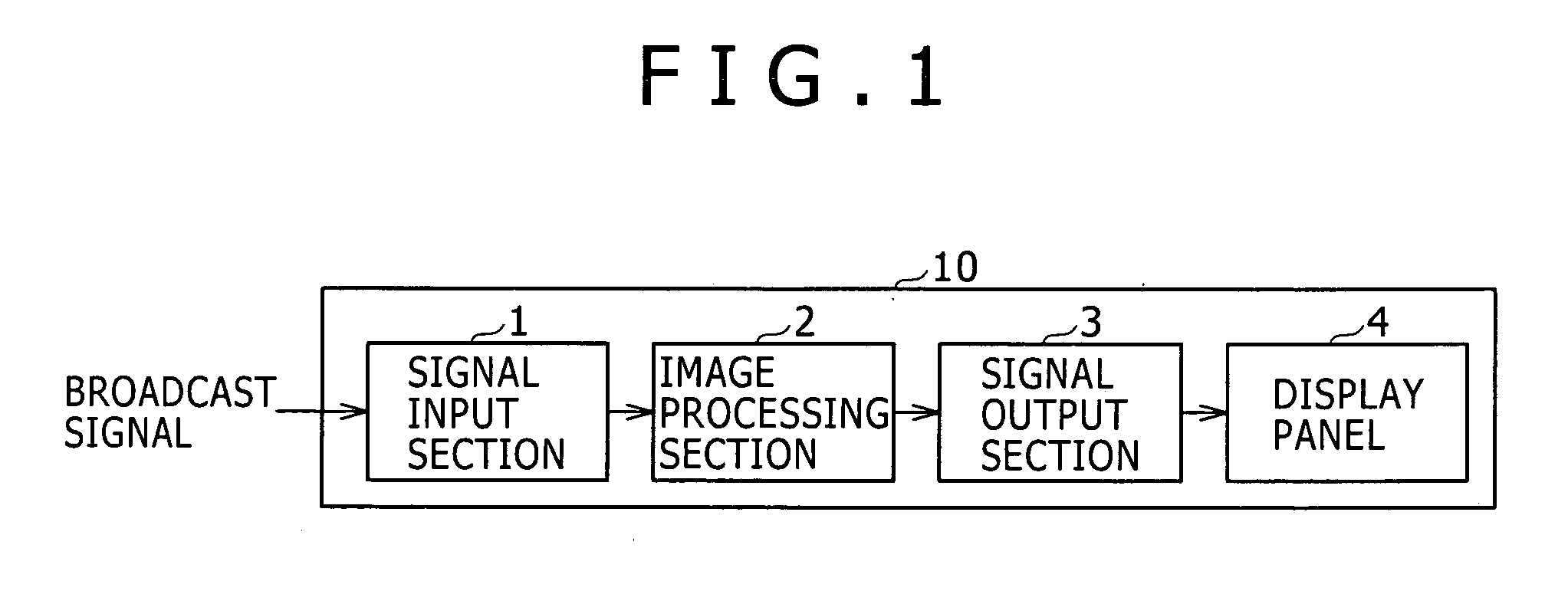
[0041]FIG. 1 is a block diagram showing a typical entire configuration of an image display apparatus 10 according to a first embodiment of the present invention. As shown in the figure, the image display apparatus 10 employs a signal input section 1, an image processing section 2, a signal output section 3 and a display panel 4. The display panel 4 is a typical concrete implementation of a display section provided by the present invention whereas the image processing section 2 is a typical concrete implementation of an image processing apparatus provided by the present invention.

[0042]A typical example of the image display apparatus 10 is a TV set. The signal input section 1 typically receives a broadcast signal. Then, the signal input section 1 carries out a process to split the broadcast signal into a luminance signal also referred to as a Y signal and a color-difference signal which is a U signal and a V signal. Finally, the signal inpu...

second embodiment

[0083]Next, an image display apparatus according to a second embodiment of the present invention is explained. It is to be noted that, in the image display apparatus according to the second embodiment, components virtually identical with their respective counterparts employed in the image display apparatus according to the first embodiment are denoted by the same reference numerals and the same reference notations as the counterparts. In addition, explanations of the identical components are properly omitted in order to avoid duplications of descriptions.

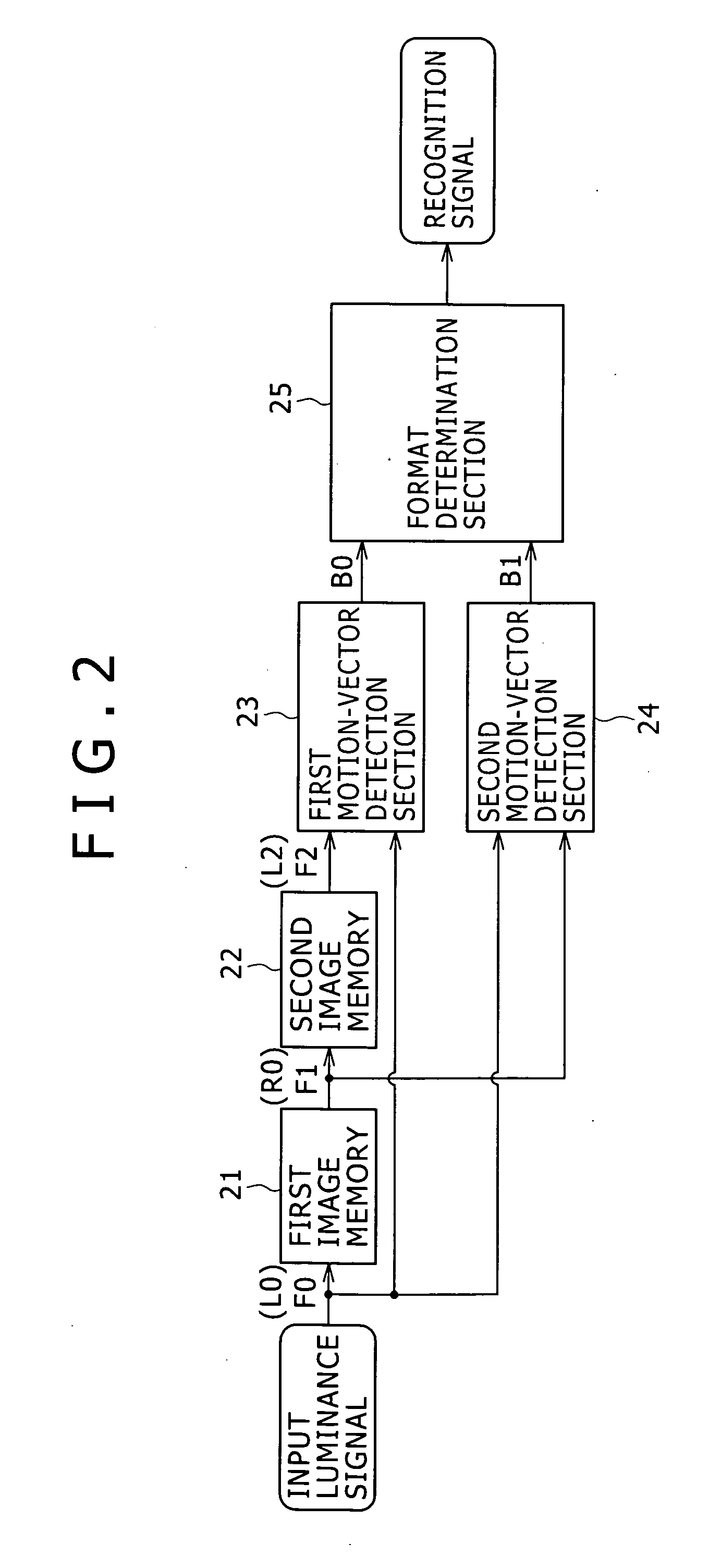
[0084]FIG. 7 is a block diagram showing the configuration of an image processing section 2 according to the second embodiment. The configuration of the image processing section 2 shown in FIG. 7 is different from the configuration of the image processing section 2 according to the first embodiment shown in the block diagram of FIG. 2 in that the second embodiment has an image interpolation section 31. In addition, the second embodim...


PUM


Abstract

Disclosed herein is an image processing apparatus including, a motion-vector detection section configured to find a motion vector corresponding to an image disparity existing between left and right eyes to appear as a disparity in images, and a format determination section configured to determine whether the input image signal is a signal of the 3-dimensional image format or a signal of the 2-dimensional image format.

Description

BACKGROUND OF THE INVENTION[0001]1. Field of the Invention[0002]The present invention relates to an image processing apparatus capable of recognizing the image format of an input image signal, an image processing method adopted by the image processing apparatus and an image display apparatus employing the image processing apparatus.[0003]2. Description of the Related Art[0004]Since a time in the past, there has been known a 3-dimensional image display apparatus adopting a spectacle system. The 3-dimensional image display apparatus implements binocular visions by showing separate images with disparities to both the eyes of an observer who is wearing a special stereoptican based on optical polarization and / or crystal shutters.[0005]In addition, there has also been known a naked-eye 3-dimensional image display apparatus adopting a parallax barrier system or a lenticular system. This naked-eye 3-dimensional image display apparatus is capable of implementing binocular visions for naked e...

Claims


Application Information

Patent Timeline
IPC IPC(8): H04N15/00H04N5/14
CPCH04N5/144H04N2213/007H04N13/0048H04N13/161
Inventor IHARA, TOSHINORIASANO, MITSUYASU
Owner SATURN LICENSING LLC
Learn More