Eureka AIR delivers breakthrough ideas for toughest innovation challenges, trusted by R&D personnel around the world.

Oil-cooler-equipped radiator

Inactive Publication Date: 2006-12-14
CALSONIC KANSEI CORP
View PDF7 Cites 14 Cited by
  • Summary
  • Abstract
  • Description
  • Claims
  • Application Information

AI Technical Summary

Benefits of technology

[0012] Therefore, along with the heating up of the tank, the heat exchanger is heated up via the heat conduction portion, so that the heat conduction portion of the pipe connector and the inside of the tank can be favorably brazed, and moreover the entire oil cooler including the pipe connector can be smoothly heated up to be brazed.

Problems solved by technology

However, in the conventional oil-cooler-equipped radiator, for example, when the all-aluminum radiator is brazed, a pipe connector, which is a fixing portion of the oil cooler on the tank, is not smoothly heated up, which causes a problem of generating a brazing failure.
If a time period of brazing is extended, zinc diffusion in a radiator tube may proceed and degrade the corrosion resistance of the radiator tube, which is not favorable.

Method used


Image

  • Oil-cooler-equipped radiator
  • Oil-cooler-equipped radiator
  • Oil-cooler-equipped radiator

Examples


Embodiment Construction

[0025] Hereinafter, an embodiment of an oil-cooler-equipped radiator according to the present invention will be described with accompanying drawings.

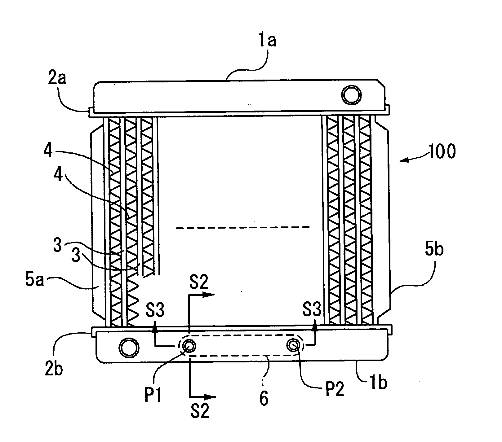
[0026] As shown in FIG. 1, the oil-cooler-equipped radiator according to the embodiment includes a pair of seat plates 2a and 2b provided at an upper side of a radiator 100 and at a lower side of the radiator 100 with upper and lower tanks 1a and 1b, respectively; tubes 3 and corrugated fins 4 alternately disposed between the seat plates 2a and 2b; and reinforcements 5a and 5b for connecting both end portions of the seat plates 2a and 2b at their both sides so as to reinforce them.

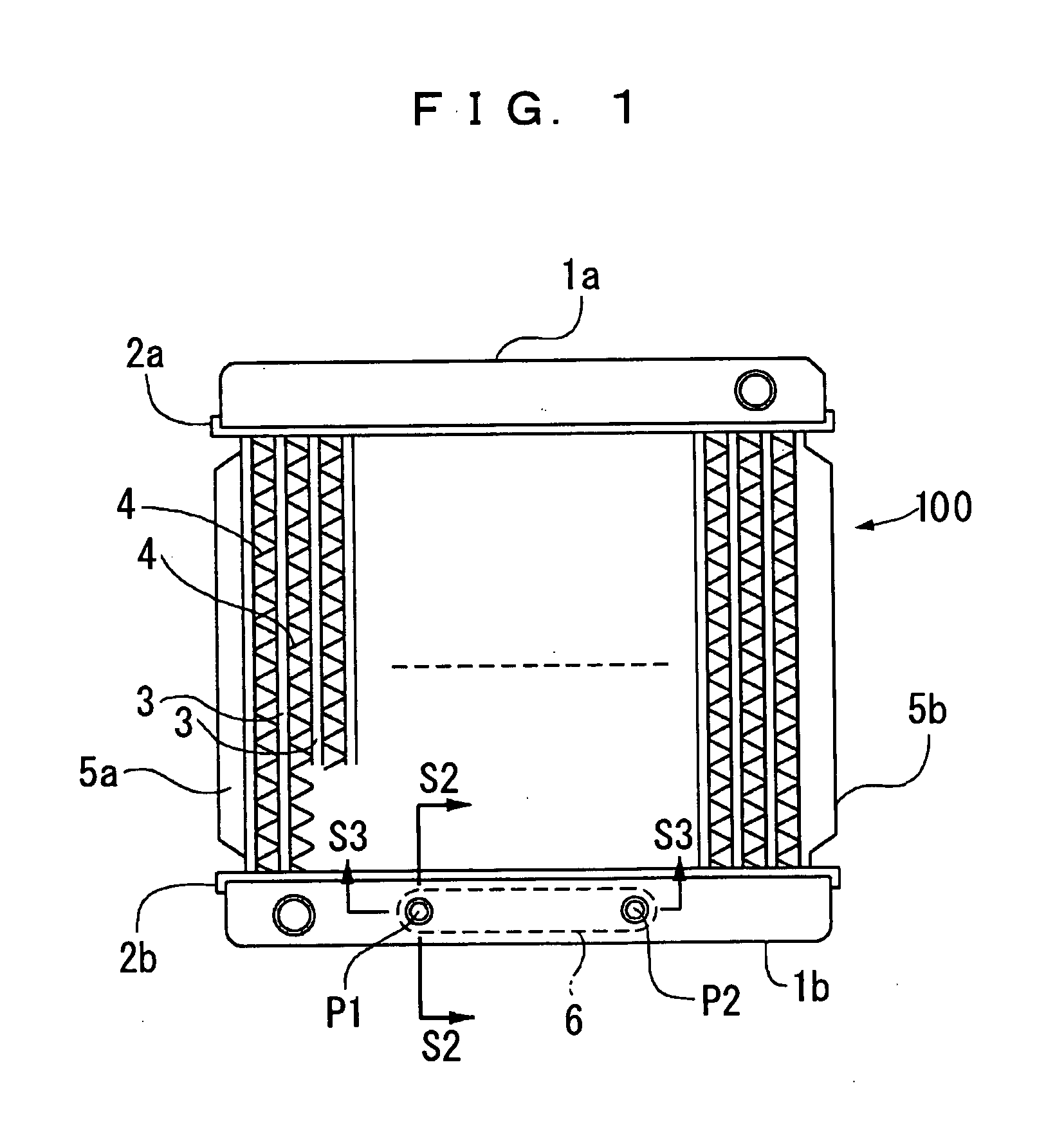
[0027] An oil cooler 6, which will be described in detail later, is accommodated in the lower tank 1b, and all the components including the oil cooler 6 and the lower tank 1b are made of aluminum.

[0028] As shown in FIGS. 2 and 3, the oil cooler 6 according to the embodiment has a heat exchanger 8 including a plurality of element units 7 stacked in a state c...


PUM


Abstract

An oil cooler includes a heat exchanger having a plurality of element units stacked in a state communicating with each other, pipe connectors coupled to the heat exchanger in a state communicating with spaces formed respectively at both end portions in the longitudinal direction of the heat exchanger, and a pair of connecting pipes communicating with the spaces from connecting pipe attaching holes formed on the tank via cylindrical portions of the pipe connectors. The cylindrical portions are fixed respectively to rings provided on the outside of the tank at the connecting pipe attaching holes, and joint portions thereof are formed to be exposed to the outside of the tank.

Description

BACKGROUND OF THE INVENTION [0001] 1. Field of the Invention [0002] The present invention relates to an oil-cooler-equipped radiator which is brazed while an oil cooler is accommodated in a tank of the radiator for a motor vehicle, and the like. [0003] 2. Description of the Related Art [0004] Conventionally, techniques about an oil-cooler-equipped radiator in which an oil cooler is accommodated in a tank of the radiator have been known, which are disclosed in Japanese Patent Application Laid-open Nos. 2001-153586, Hei 10-73393, and Hei 11-142089. [0005] Also, an all-aluminum radiator in which a tank and core portions of a radiator are formed of aluminum has been developed. In this type of radiator, brazing of a tank and an oil cooler is performed while the oil cooler is accommodated in the tank. [0006] However, in the conventional oil-cooler-equipped radiator, for example, when the all-aluminum radiator is brazed, a pipe connector, which is a fixing portion of the oil cooler on the ...

Claims


Application Information

Patent Timeline
IPC IPC(8): F28D7/10
CPCF28D9/0043F28F2240/00F28F9/0234
Inventor OKURA, HIROYUKITOCHIGI, KENJIMATSUDAIRA, NORIMITSUNAKAKOMI, TAKAHIRO
Owner CALSONIC KANSEI CORP
Why Eureka
Eureka Blog
Learn More