Multi-Drop Flow Control Valve System

a flow control valve and flow control technology, applied in the direction of machines/engines, sealing/packing, borehole/well accessories, etc., can solve the problems of cost, reliability, and wellbore diameter adversely, and achieve the effect of facilitating radial flow

Inactive Publication Date: 2006-12-14
SCHLUMBERGER TECH CORP
View PDF20 Cites 61 Cited by
  • Summary
  • Abstract
  • Description
  • Claims
  • Application Information

AI Technical Summary

Benefits of technology

[0010] The initial position may be either an open, closed, or a choke position. In the open position an aperture in the tubular housing is uncovered by the choke permitting radial flow to and from the tubing via the valve. In the closed position, the aperture through the housing is covered preventing radial flow, and in the choked position the choke partially covers the aperture through the housing. The choke may be a slidable sleeve having an orifice for alignment with the aperture through the housing to facilitate radial flow.

Problems solved by technology

The multiplicity of control lines required heretofore adversely affects cost, reliability, and wellbore diameter.

Method used


Image

  • Multi-Drop Flow Control Valve System
  • Multi-Drop Flow Control Valve System
  • Multi-Drop Flow Control Valve System

Examples


Embodiment Construction

[0021] Refer now to the drawings wherein depicted elements are not necessarily shown to scale and wherein like or similar elements are designated by the same reference numeral through the several views.

[0022] As used herein, the terms “up” and “down”; “upper” and “lower”; “upstream” and “downstream” and other like terms indicating relative positions to a given point or element are utilized to more clearly describe some elements of the embodiments of the invention. Commonly, these terms relate to a reference point as the surface from which drilling operations are initiated as being the top point and the total depth of the well being the lowest point.

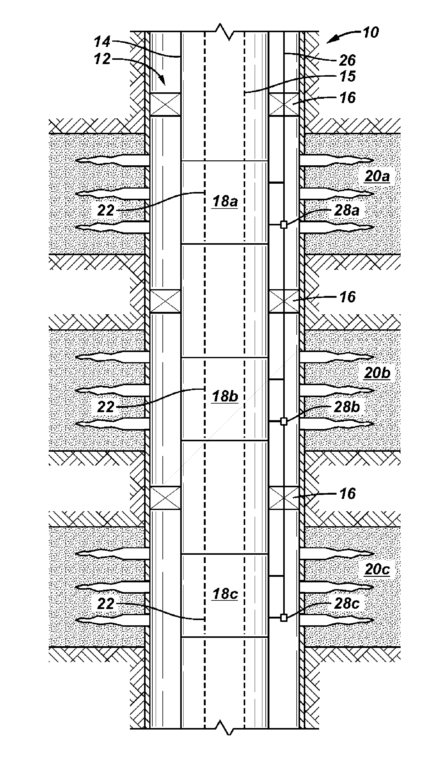
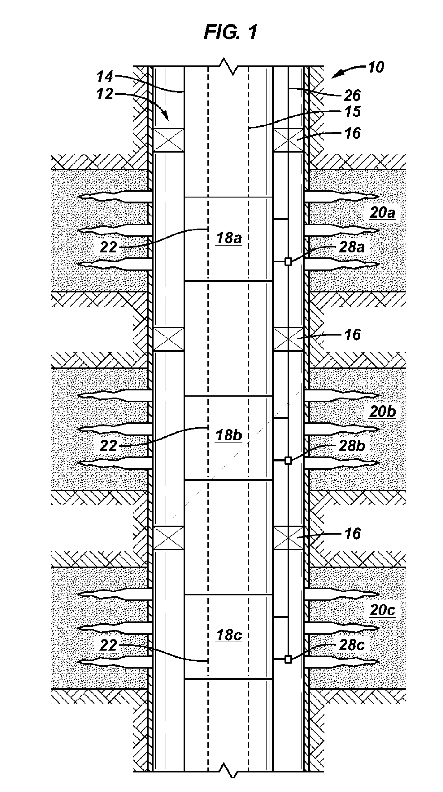
[0023]FIG. 1 is a schematic view of a single control line, multi-drop flow control valve system, generally denoted by the numeral 10, in accordance to one embodiment of the present invention positioned in a wellbore 12. The completion string includes a tubing 14 having a bore 15 (e.g., a production tubing or other type of tubing or pipe...


PUM


Abstract

A multi-drop flow control valve system having a plurality of hydraulically actuated flow control valve, each valve set in an initial operating position. The flow control valves are connected to a hydraulic control line in sequence, wherein the second flow control valve is below the first flow control valve and so on. Wherein a first hydraulic pressure in the control line will operate at least the first flow control valve to an actuated position and a second hydraulic pressure greater than the first hydraulic pressure will operate at least the first and second flow control valves to actuated positions. It may be desired for each of the control valves to be biased in the initial position when the hydraulic pressure is less than a base pressure.

Description

FIELD OF THE INVENTION [0001] The present invention relates in general to a system for controlling the flow of fluid radially to and from a string of tubing at multiple locations. More particularly, the invention relates to a system for controlling via a single control line the radial flow of fluid to and from a string of tubing at multiple locations. BACKGROUND [0002] In completing a well, one or more zones may be perforated to enable production and / or injection of fluids. Completion equipment including flow control devices, tubing, packers, and other devices may be installed in various positions in the well to manage the respective zones. In operating the well it is necessary to actuate the flow control device for each zone. [0003] Typically each flow control device is actuated hydraulically, electrically, mechanically or pneumatically via a separate control line routed to each flow control device. For example, a well having four productions zones, each managed by a single hydraul...

Claims


Application Information

Patent Timeline
Patent Type & Authority Applications(United States)
IPC IPC(8): E21B34/10
CPCE21B2034/007E21B34/10E21B2200/06Y10T137/86928
Inventor DWIVEDI, ALOKPARKS, STEPHEN
Owner SCHLUMBERGER TECH CORP
Why Eureka
Try Eureka