
Method and apparatus for friction reduction in a downhole tool

a friction reduction and downhole tool technology, applied in the field of downhole tools, can solve the problems of time and money, partial ineffective pumping process, wireline installation,

Active Publication Date: 2006-12-14
WEATHERFORD TECH HLDG LLC
View PDF13 Cites 74 Cited by
  • Summary
  • Abstract
  • Description
  • Claims
  • Application Information

AI Technical Summary

Benefits of technology

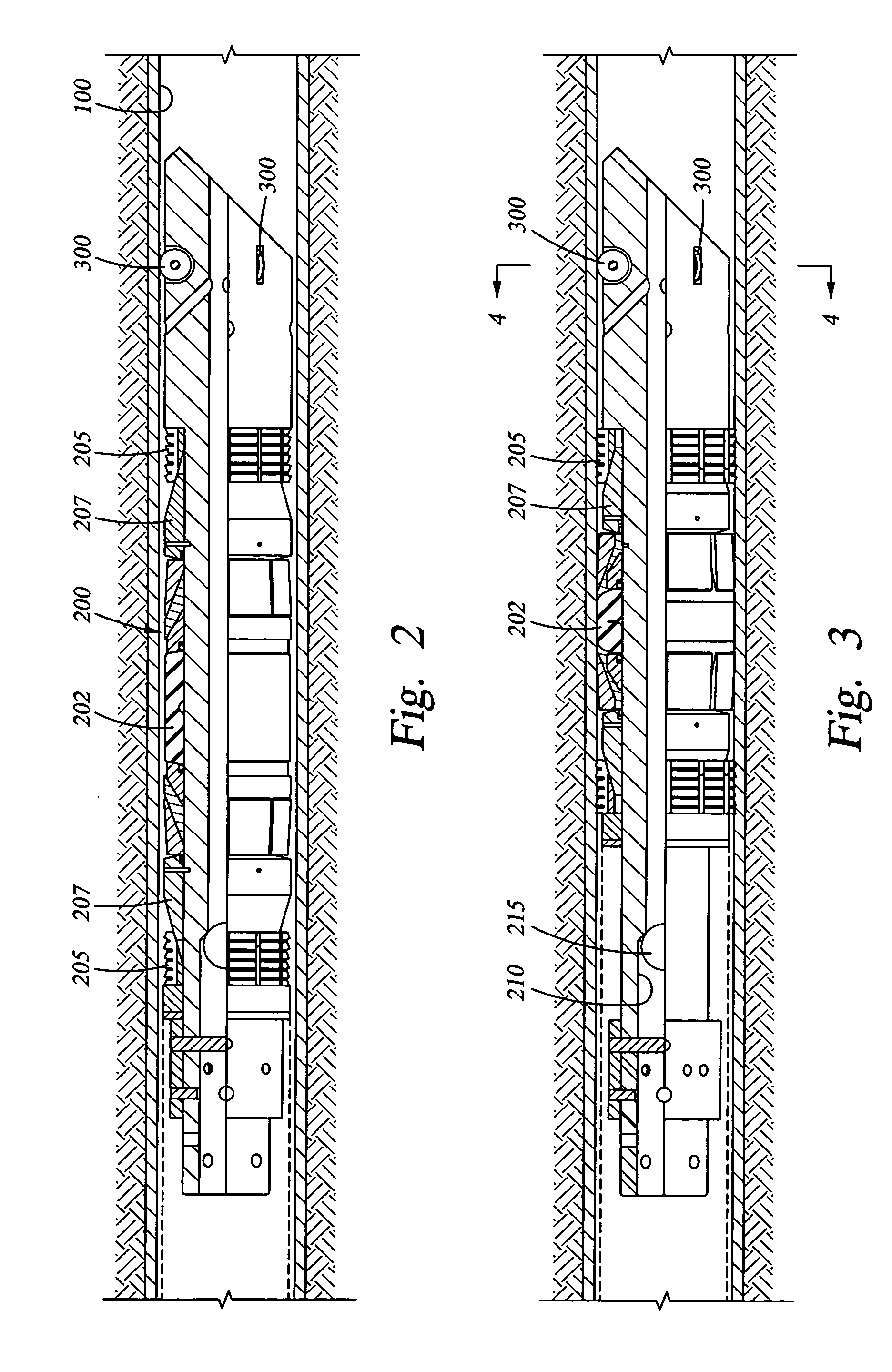
[0008] The invention relates to a system for facilitating the insertion of a tool into a wellbore, especially a non-vertical wellbore. In one embodiment a tool is fixable in a wellbore and includes centralizing, friction-reducing members that serve to keep the body of the tool off the walls of the wellbore wall. In another embodiment the tool includes a wiper ring that partially fills an annular area formed between the centered tool and the wellbore walls. The surface of the ring facing the upper end of the wellbore provides fluid resisting piston surface and permits the centered tool to be pumped down the wellbore more effectively.

Problems solved by technology

In operations requiring many tools to be placed in the wellbore, like fracturing operations including multiple zones, wireline installation saves time and money.
Problems with wireline installations arise with non-vertical wellbores simply because gravity is not available to help urge the tool down the wellbore.
This is partially effective but due to the position of the tool on the low side of the wellbore, a large annular gap extends between the top of the tool and the upper wall of the wellbore, making the pumping process partially ineffective.
However, tractors are expensive, cannot be left in a well and add another layer of complication to a tool installation job.

Method used


Image

  • Method and apparatus for friction reduction in a downhole tool
  • Method and apparatus for friction reduction in a downhole tool
  • Method and apparatus for friction reduction in a downhole tool

Examples


Embodiment Construction

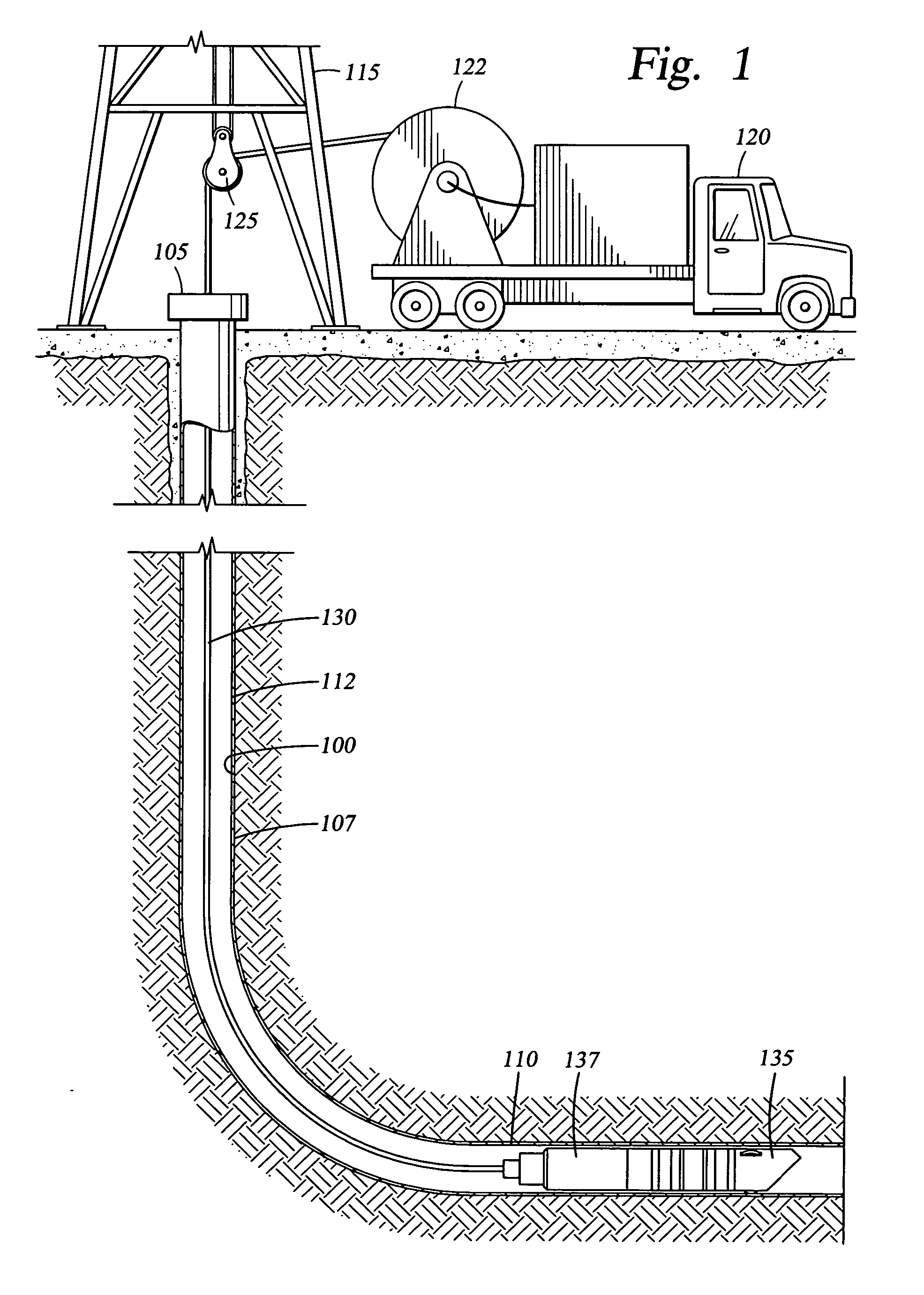
[0017]FIG. 1 shows a typical completed well with a wellbore 100, a wellhead 105, a vertical wellbore section 107 and a non-vertical wellbore section 110. The wellbore is lined with casing 112. Installed over the well is a rig 115 placed there to facilitate the insertion of a tool or tools into the wellbore. A truck 120 is shown with a reel 122 of wireline that can be directly placed in the wellbore via a block and tackle assembly 125 of the rig.

[0018] At a lower end of the wireline 130, in the non-vertical section 110 of the wellbore is a tool 135. Like those described herein, the tool is designed to be located via the wireline at a predetermined location in the wellbore and then fixed to the wall of the wellbore by remotely actuating a slip and cone assembly (not shown) built onto the tool. In one instance, the downhole tool is a plug with a central bore that can be temporarily blocked in a single direction during an operation. In a wireline installation, the plug is typically act...


PUM


Abstract

A system for facilitating the insertion of a tool into a wellbore, especially a non-vertical wellbore. In one embodiment a tool is fixable in a wellbore and includes centralizing, friction-reducing members that serve to keep the body of the tool off the walls of the wellbore. In another embodiment the tool includes a wiper ring that partially fills an annular area formed between the centered tool and the wellbore walls. The surface of the ring facing the upper end of the wellbore provides fluid resisting piston surface and permits the centered tool to be pumped down the wellbore more effectively.

Description

FIELD OF THE INVENTION [0001] The present invention relates to downhole tools. More specifically, the invention relates to tools run into a wellbore and apparatus and methods to facilitate their insertion. More particularly still, the invention relates to a centering device having friction reducing members to reduce contact of a tool with the walls of a non-vertical wellbore. The invention also facilitates “pumping” a tool into a wellbore with fluid when gravity is not available. BACKGROUND OF THE INVENTION [0002] Various operations require tools to be inserted into a well and fixed there temporarily. In some instances, packers are run into a wellbore and then set using slips and cones that fix the packer at a predetermined location to isolate an annular area of the bore. In other instances, bridge plugs or “frac” plugs are similarly installed to temporarily block the wellbore and provide a barrier against which pressure can be developed to treat a hydrocarbon-bearing formation adja...

Claims


Application Information

Patent Timeline
IPC IPC(8): E21B19/00E21B4/00E21B23/00
CPCE21B17/1042E21B23/08E21B17/1057E21B23/00E21B33/12
Inventor TURLEY, ROCKY A.MCKEACHNIE, JOHN W.
Owner WEATHERFORD TECH HLDG LLC
Learn More