Wiring harness holding device

a holding device and wiring harness technology, applied in the direction of insulated conductors, electric/fluid circuits, cables, etc., can solve the problems of reducing the size of the wiring harness holding device, so as to reduce the production of looseness in the wiring harness, reduce the stress acting on the wiring harness, and improve general-purpose properties

Inactive Publication Date: 2006-12-14
YAZAKI CORP
View PDF6 Cites 5 Cited by
  • Summary
  • Abstract
  • Description
  • Claims
  • Application Information

AI Technical Summary

Benefits of technology

[0052] According to the wiring harness holding device described in (12) above, since the reinforcement member is made up of the corrugated tube, the corrugated tube can not only be guided in the swiveling direction but also be prevented from being dislodged from the opening of the exit hole by the ridges and grooves formed on the outer surface of the corrugated tube and the guide rail formed at the opening of the exit hole.
[0053] According to the wiring harness holding device described in (13) above, a twisting rotation is produced mainly in the wiring harness accommodated in the shaft hole in association with the swiveling of the wiring harness which is caused to exit from the exit hole, whereby stress acting on the wiring harness can be relaxed.
[0054] According to the wiring harness holding device described in (14) above, the wiring harness is fixed in such a state that part of the wiring harness follows a direction which intersects the sliding direction at right angles in the vicinity of the stationary side holding portion, whereby the behavior of the wiring harness is stabilized between the movable side holding portion and the stationary side holding portion which are disposed in such a manner as to be spaced apart in the direction which intersects the sliding direction of the movable structure at right angles, thereby making it possible to suppress the production of looseness in the wiring harness.
[0055] According to the wiring harness holding device described in (15) above, the wiring harness holding device can be applied to various types of movable structures having different sliding amounts by properly adjusting the distance over which the movable side holding portion and the stationary side holding portion are spaced apart in the direction which intersects the sliding direction at right angles within the scope of a capability of absorbing the excess length through the swiveling of the wiring harness, and therefore, is superior with respect to general-purpose properties.
[0056] In the wiring harness holding device for holding a wiring harness laid out in such a manner as to extend between the stationary structure and the movable structure, the wiring harness holding device can be provided which can absorb the excess length produced in association with the sliding movement of the movable structure and which is small in size and superior with respect to the general-purpose properties.

Problems solved by technology

When attempting to install electric equipment at the sliding seat or sliding door, a wiring harness needs to be laid out in such a manner as to extend between the electric equipment and the vehicle body, and when this is actually carried out, there has been caused a difficulty in accommodating the wiring harness.
For example, since a sliding seat used on a currently popular minivan slides largely, an excess length is generated in a wiring harness 6 in association with the sliding movement of the sliding seat 5 as shown in FIG. 14, being likely to cause a problem that the occupant is caught at his or her leg by the wiring harness 6 which is loosened due to the excess length so produced.
It appears that this causes a disadvantage in reducing the size of the wiring harness holding device.
Namely, in a wiring harness of a large diameter such as one in which a general electric wire (an earth wire) needing a current capacity is provided in parallel, the permissible radius of curvature tends to be increased, and since the excess length L also needs to be set large in association with the increase in the radius of curvature, this construction tends to be a disadvantage in making the wiring harness holding device smaller in its size.
In addition, the excess length is designed to meet the sliding stroke of the sliding seat and the radius of curvature of the wiring harness exclusively for each model, and this causes a problem that this wiring harness holding device is inferior with respect to general-purpose properties.

Method used


Image

  • Wiring harness holding device
  • Wiring harness holding device
  • Wiring harness holding device

Examples


first embodiment

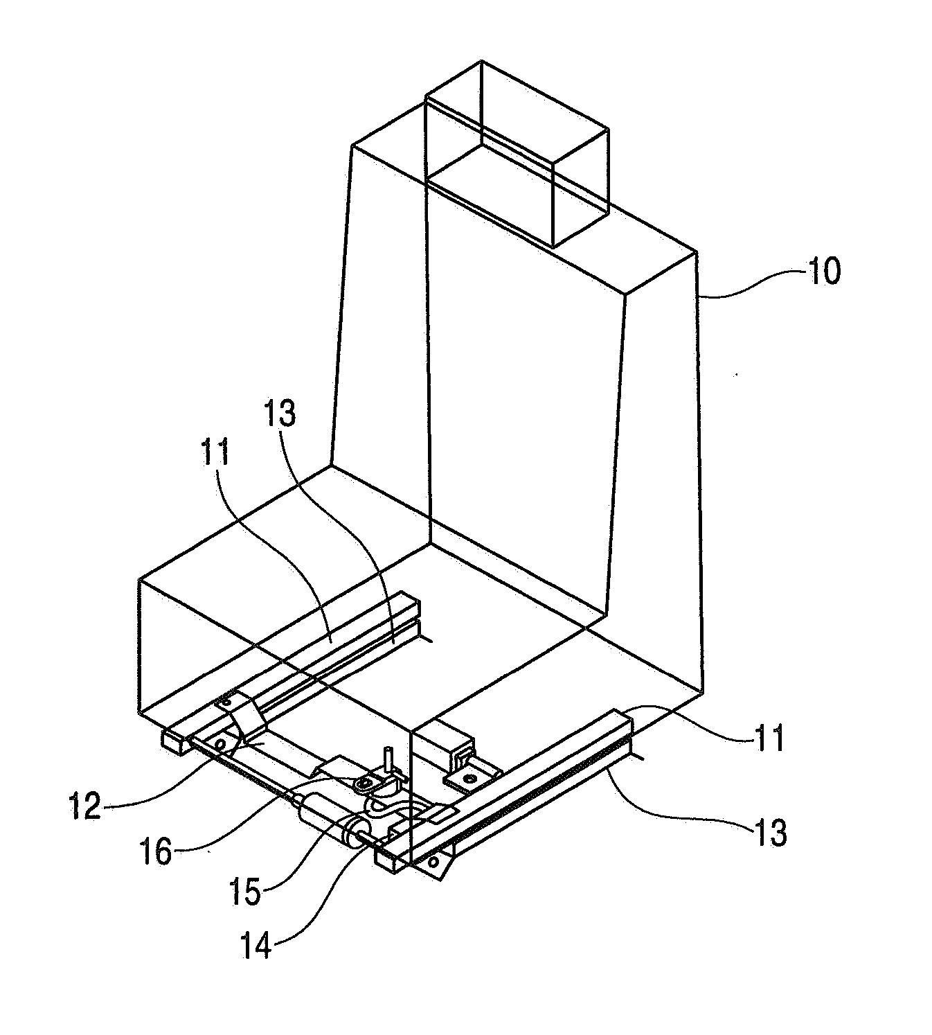
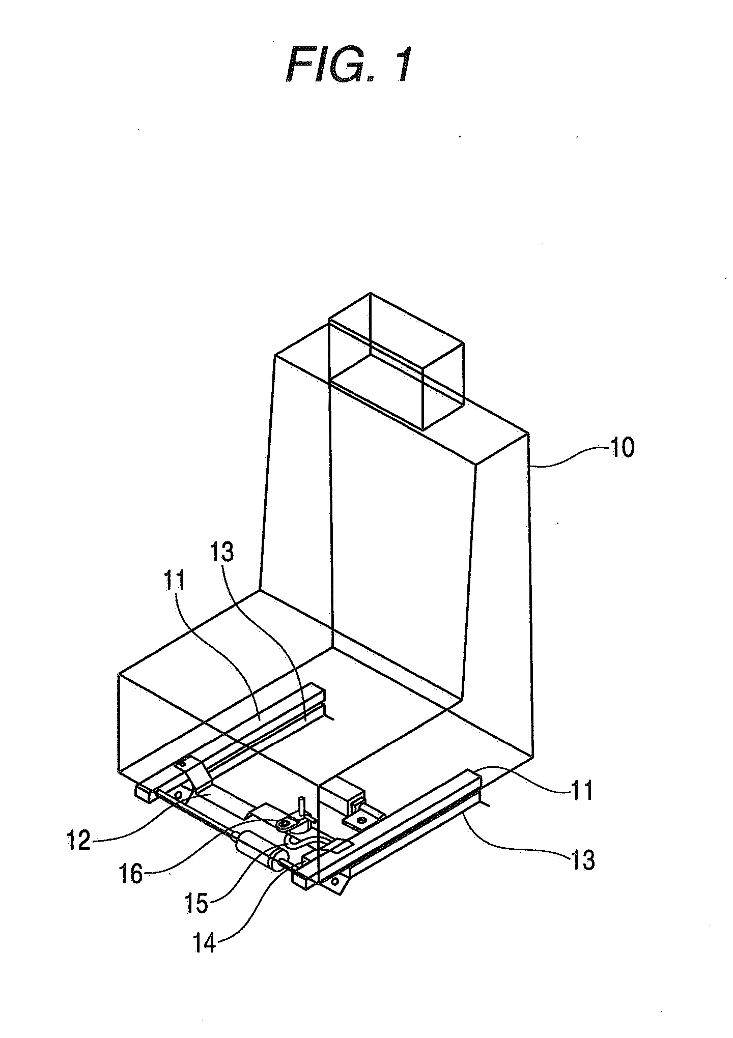
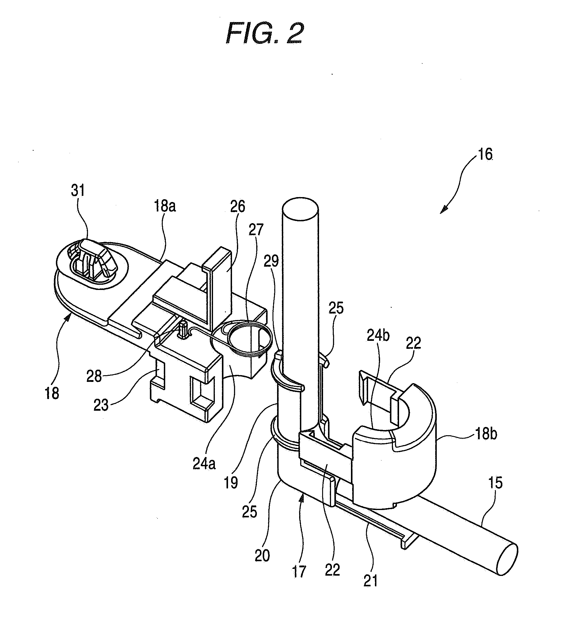
[0074]FIG. 1 is a perspective view of a vehicle sliding seat to which a wiring harness holding device of the invention is applied, FIG. 2 is an exploded perspective view of a movable side holding portion of the wiring harness holding device shown in FIG. 1, FIG. 3 is a perspective view showing an external appearance of the movable side holding portion which has been assembled completely, and FIG. 4 shows plan views of the vehicle sliding seat as viewed from a bottom side thereof which explain the operation of the wiring harness holding device shown in FIG. 1.

[0075] Firstly, a sliding construction of a vehicle sliding seat will be described.

[0076] As shown in FIG. 1, a pair of sliders 11 which extend in a back and forth or longitudinal direction of a vehicle body (not shown) are mounted on a bottom side of a vehicle sliding seat (a movable structure) 10 in such a manner as to be spaced apart in a width direction of the seat 10, and front end portions of the individual sliders 11 are...

second embodiment

[0096] Next, referring to FIG. 5, the invention will be described below.

[0097]FIG. 5 is a perspective view of a movable side holding portion of a wiring harness holding device according to a second embodiment of the invention. Note that like reference numerals will be imparted to like or corresponding members to those of the first embodiment that has been described above, so as to omit the description thereof.

[0098] As shown in FIG. 5, the wiring harness holding device of the second embodiment is such that in the movable side holding portion 16 of the wiring harness holding device of the first embodiment that has been described above, a restriction rib 34 is provided at an upper collar portion 25 of a shaft portion 19 of a protector 17 in such a manner as to protrude radially, and a restriction rib 35 is provided at an upper opening edge portion of a through hole 24 of a support member 18 with which the collar portion 25 is in engagement in such a manner as to be situated on the sa...

third embodiment

[0099] Next, referring to FIGS. 6 to 11, the invention will be described below.

[0100]FIG. 6 is an exploded perspective view of a movable side holding portion of a wiring harness holding device of a third embodiment of the invention, FIG. 7 is a perspective view showing an external appearance of part of the movable side holding portion shown in FIG. 6 which explains an assembling procedure thereof, FIG. 8 is a perspective view showing an external view of the remaining part of the movable side holding portion shown in FIG. 6 which explains an assembling procedure thereof, and FIG. 9 is a perspective view showing an external view of the movable side holding portion shown in FIG. 6 which has been assembled completely. Note that like reference numerals will be imparted to like members to those of the first embodiment that has been described before, so as to omit the description thereof.

[0101] In a wiring harness holding device of this embodiment, a movable side holding portion 56 shown ...


PUM


Abstract

A wiring harness holding device for holding a wiring harness laid between a stationary structure and a movable structure slidably provided to the stationary structure, includes a movable side holding portion that holds one portion of the wiring harness on the movable structure, and a stationary side holding portion that holds another portion of the wiring harness on the stationary structure. The movable side holding portion holds the wiring harness so that the wiring harness derived from the movable side holding portion towards the stationary side holding portion swivels around the movable side holding portion in association with the sliding movement of the movable structure.

Description

BACKGROUND OF THE INVENTION [0001] The present invention relates to a wiring harness holding device for a wiring harness which is laid out in such a manner as to extend between a stationary structure such as a vehicle body of a motor vehicle and a movable structure such as a sliding seat or sliding door which slides relative to the vehicle body and more particularly to a wiring harness holding device for absorbing an excess length of the wiring harness which is produced in association with the sliding of the movable structure. [0002] Among automotive components, sliding seats and sliding doors are components which slide largely relative to the vehicle body. When attempting to install electric equipment at the sliding seat or sliding door, a wiring harness needs to be laid out in such a manner as to extend between the electric equipment and the vehicle body, and when this is actually carried out, there has been caused a difficulty in accommodating the wiring harness. [0003] For examp...

Claims


Application Information

Patent Timeline
Patent Type & Authority Applications(United States)
IPC IPC(8): H02G3/04
CPCB60R16/027B60R16/0215
Inventor TSUKAMOTO, MASASHISATO, KUNIHIKOITO, MASAHIRO
Owner YAZAKI CORP
Why Eureka
Try Eureka