Axial air gap type electric motor

a technology of electric motor and air gap, which is applied in the direction of magnetic circuit rotating parts, mechanical equipment, magnetic circuit shape/form/construction, etc., can solve the problems of large vibration and noise generation

Active Publication Date: 2006-12-14
FUJITSU GENERAL LTD
View PDF5 Cites 29 Cited by
  • Summary
  • Abstract
  • Description
  • Claims
  • Application Information

AI Technical Summary

Benefits of technology

[0034] In accordance with the axial air gap type electric motor in the present invention using the above sections, magnetic pre-pressurizing section for pre-pressurizing the inner ring in an axial direction by a difference of magnetic force of the axial direction in one of the air gaps and the other of the air gaps is arranged in the inventions relating to aspects 1 and 2. Since no inner ring is pre-pressurized by a mechanical mechanism, the rotating shaft, i.e., the inner ring of the radial ball bearing fixed to this rotating shaft can be pre-pressurized in the rotating axis direction without arranging an additional part. Thus, a vibration and noises can be reduced.
[0042] In the invention relating to aspect 10, the magnetic pre-pressurizing section is constructed by a difference of magnetic permeability in the one air gap and magnetic permeability in the other air gap. Thus, for example, the pre-pressurization can be easily adjusted in the manufacturing process by sticking a magnetic sheet having a magnetic permeability different from that of the air gap onto a tease face and a permanent magnet face. Therefore, electric motors of many kinds different in pre-pressurization can be easily manufactured.

Problems solved by technology

Thus, there is a case in which large vibration and noises are generated.

Method used


Image

  • Axial air gap type electric motor
  • Axial air gap type electric motor
  • Axial air gap type electric motor

Examples


embodiment 1

[Embodiment 1]

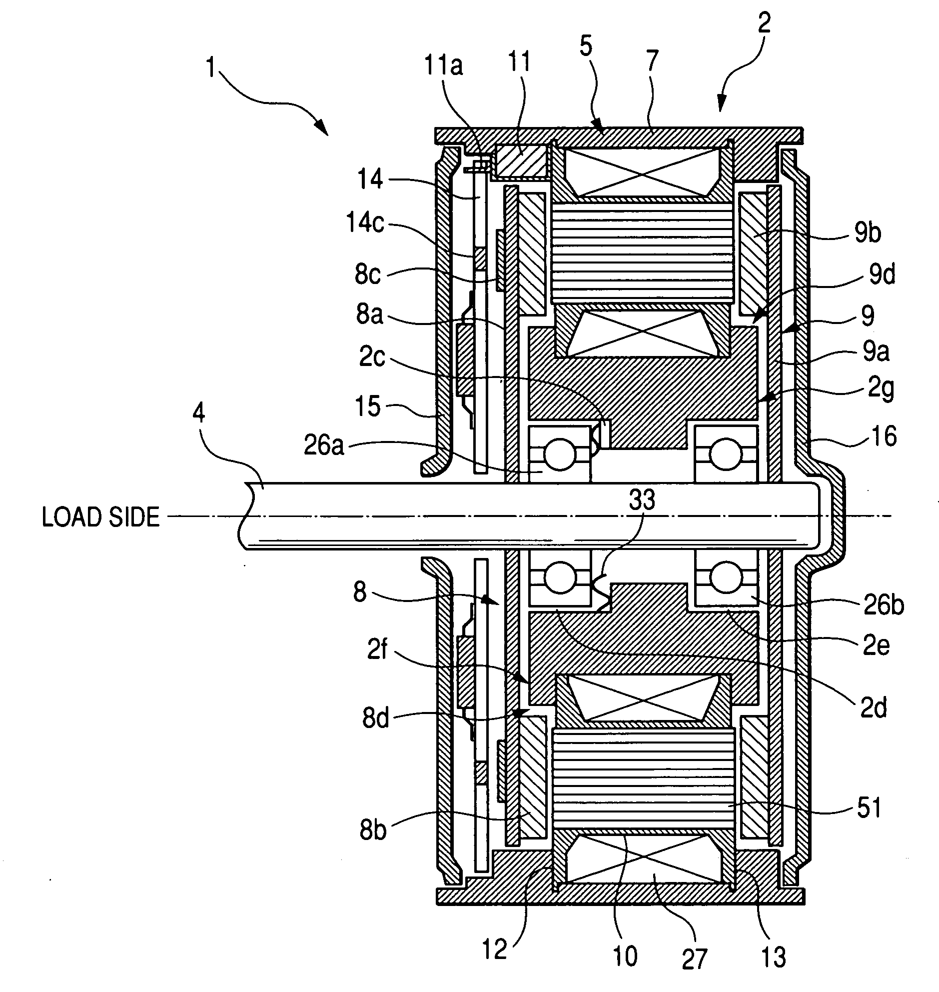
[0059] As shown in FIG. 1, the axial air gap type electric motor 1 of three phases and nine slots in the present invention includes a stator 2 approximately formed in a disk shape, and a pair of rotors 8, 9 oppositely arranged with a predetermined air gap on both sides of the stator 2. The rotors 8, 9 commonly have the same rotating shaft 4. The stator 2 has a first bearing 26a and a second bearing 26b coaxially inserted on its inner circumferential side, and constructed by a radial ball bearing for supporting the rotating shaft 4.

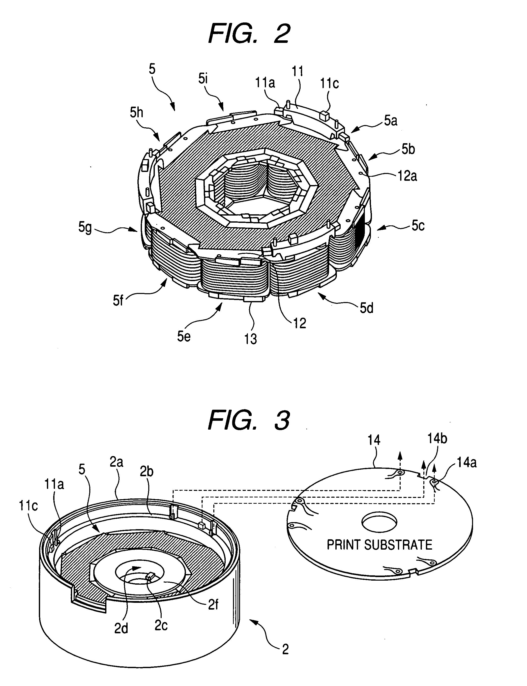
[0060] A bracket cover 15, a print substrate 14 mounting a driving circuit of the motor, the rotor 8, the stator 2, the rotor 9 and a bracket cover 16 are respectively sequentially arranged in a circular shape with the rotating shaft 4 as a center in this electric motor.

[0061] A Hall element 14c is arranged in the print substrate 14 opposed to a permanent magnet 8c for detecting the position of the rotor 8, and detects the rotating position...

embodiment 2

[Embodiment 2]

[0116] Another embodiment will next be explained by using FIG. 10. FIG. 10 is a cross-sectional view of an axial air gap type electric motor using the present invention. This axial air gap type electric motor has the same structure as the structure of embodiment 1. Therefore, parts having the same functions are designated by the same numbers, and their detailed explanations are omitted.

[0117] A large difference between this embodiment and embodiment 1 is arranging places of the first bearing 26a and the second bearing 26b. In embodiment 1, the first bearing 26a and the second bearing 26b are arranged within the stator. However, in this embodiment, the first bearing 26a and the second bearing 26b are respectively arranged in respective mounting portions 15a, 16b of two brackets 15, 16.

[0118] The brackets 15, 16 are press-fitted into the stator 2 from its side face. Therefore, the two brackets and the stator 2 attain a fixed state. Further, the mounting portions 15a, 1...


PUM


Abstract

A magnetic pre-pressurizing section for pre-pressurizing the inner ring of the bearing in the axial direction by a difference of magnetic forces of permanent magnets of the two rotors is arranged. The magnetic pre-pressurizing section is constructed by a difference of a magnetizing amount for forming permanent magnets 8b, 9b arranged in the respective rotors. The magnetic pre-pressurizing section is also constructed by a difference of distances of an air gap L1 of a stator 2 and a permanent magnet 8b1, and an air gap L2 of the stator 2 and a permanent magnet 9b1. The magnetic pre-pressurizing section is also constructed by a difference of thicknesses of the rotating axis direction of a permanent magnet 8b1 and a permanent magnet 9b2 arranged in the respective rotors.

Description

BACKGROUND OF THE INVENTION [0001] The present invention relates to a bearing of an axial air gap type electric motor, and more particularly, relates to a preventing structure of a vibration and noises of the bearing using a radial ball bearing. [0002] A structure for removing a play space of an inner ring and an outer ring of the ball bearing has been used as a structure for preventing a vibration and noises of the bearing using the ball bearing in the related art. Namely, this structure is a structure for arranging a pre-pressurizing means for pre-pressurizing the outer ring side to intentionally shift the inner ring and the outer ring of the ball bearing in the direction of a rotating axis. [0003] For example, this structure will be explained by using the radial gap type electric motor shown in FIG. 13. [0004] In the sectional view of FIG. 13, reference numerals 81, 82 and 83 respectively designate a rotating shaft of a motor, a rotor and a stator wound by a wire. Reference numer...

Claims


Application Information

Patent Timeline
Patent Type & Authority Applications(United States)
IPC IPC(8): H02K5/00H02K1/22
CPCH02K3/524H02K5/08H02K5/173H02K5/1735H02K2211/03H02K11/0073H02K29/08H02K2203/12H02K7/08F16C25/086H02K11/33H02K21/24
Inventor KOJIMA, TOMONORIITAGAKI, ATSUSHIMURAKAMI, MASANORITANABE, YOICHITANNO, TOSHIAKIMATSUZAKI, HIROKAZUYAMADA, MASAKI
Owner FUJITSU GENERAL LTD
Why Eureka
Try Eureka