Permanent-magnet motor

a permanent magnet and magnet technology, applied in the direction of dynamo-electric machines, magnetic circuit rotating parts, magnetic circuit shape/form/construction, etc., can solve the problems of vibration generation and noise increase due to vibration

Active Publication Date: 2006-12-14
SAMSUNG ELECTRONICS CO LTD
View PDF16 Cites 46 Cited by
  • Summary
  • Abstract
  • Description
  • Claims
  • Application Information

AI Technical Summary

Benefits of technology

[0027] The one or more rotor grooves may be formed in the shape of at least one step.
[0028] In accordance with yet another aspect, the present invention provides a permanent-magnet motor comprising a stator and a rotor having permanent magnets disposed therein, wherein the stator has one or more protrusions formed at an inner circumferential surface thereof, the protrusions being opposite to an outer circumferential surface of the rotor, to approximate sinusoidal change in magnetic flux.

Problems solved by technology

As a result, vibration is generated when the rotor 4a,4b is rotated, and noise is increased due to the vibration.

Method used


Image

  • Permanent-magnet motor
  • Permanent-magnet motor
  • Permanent-magnet motor

Examples


Embodiment Construction

[0047] Reference will now be made in detail to the embodiments of the present invention, examples of which are illustrated in the accompanying drawings, wherein like reference numerals refer to the like elements throughout. The embodiments are described below to explain the present invention by referring to the figures.

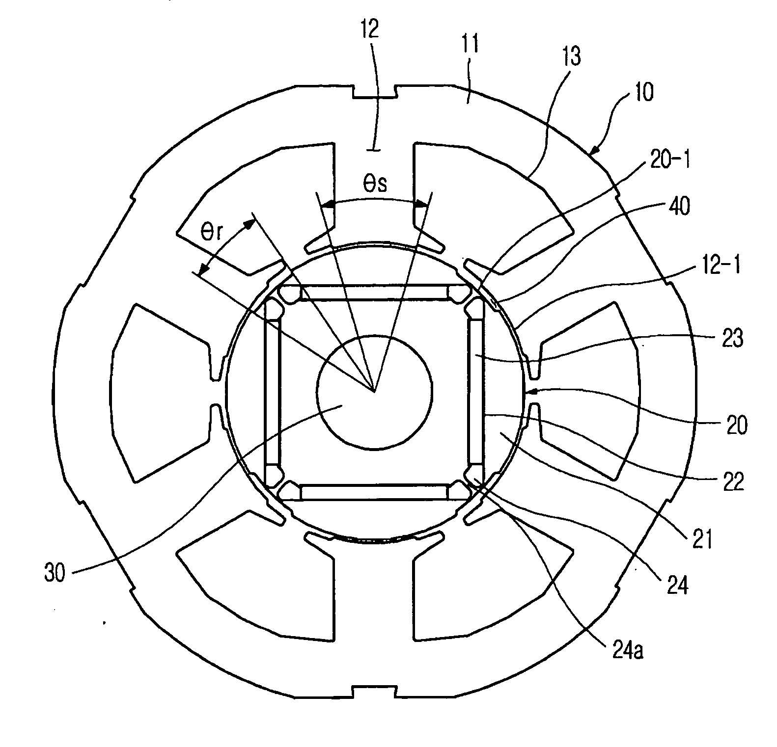
[0048]FIG. 4 is a cross-sectional view illustrating a permanent-magnet motor according to an embodiment of the present invention, and FIG. 5 is a detailed view illustrating the teeth of the stator and the surface of the rotor shown in FIG. 4.

[0049] Referring to FIG. 4, the permanent-magnet motor comprises: a stator 10 formed by stacking a plurality of magnetic steel sheets in the shape of a cylinder; a rotor 20 formed by stacking a plurality of magnetic steel sheets in the shape of a cylinder, the rotor 20 being rotatably disposed in the stator 10 while being spaced a predetermined distance from the stator 10; and a rotary shaft 30 inserted in a hollow center of the...


PUM


Abstract

A permanent-magnet motor including a rotor having permanent magnets disposed therein, and a stator, wherein an outer circumferential surface of the rotor is opposite to an inner circumferential surface of the stator, and one or both of the outer circumferential surface of the rotor and the inner circumferential surface of the stator are varied in a radial direction so as to provide a non-uniform gap between the two surfaces to approximate sinusoidal change in magnetic flux.

Description

CROSS-REFERENCE TO RELATED APPLICATIONS [0001] This application claims the benefit of Korean Patent Application No. 2005-50534, filed on Jun. 13, 2005, in the Korean Intellectual Property Office, the disclosure of which is incorporated herein by reference. BACKGROUND OF THE INVENTION [0002] 1. Field of the Invention [0003] The present invention relates to a permanent-magnet motor used in compressors of domestic refrigerators and air conditioners or other various kinds of industrial machinery, and, more particularly, to a permanent-magnet motor that is capable of approximating a back electro motive force wave to a sinusoidal wave, thereby lowering noise and increasing efficiency. [0004] 2. Description of the Related Art [0005] Generally, a permanent-magnet motor, such as a brushless DC motor, has permanent magnets mounted at a rotor core to generate a rotary driving force. Based on how the permanent magnets are mounted at the rotor core, permanent-magnet motors are classified into su...

Claims


Application Information

Patent Timeline
Patent Type & Authority Applications(United States)
IPC IPC(8): H02K1/00H02K21/12
CPCH02K1/08H02K21/16H02K1/276H02K1/146H02K1/28
Inventor KIM, YOUNG KYOUN
Owner SAMSUNG ELECTRONICS CO LTD
Why Eureka
Try Eureka