Current output type of semiconductor circuit, source driver for display drive, display device, and current output method

a technology of semiconductor circuits and source drivers, applied in the direction of electric generator control, instruments, code conversion, etc., can solve the problems of fluctuation in output current, uneven luminance, flicker,

Active Publication Date: 2006-12-14
JAPAN DISPLAY CENTRAL CO LTD
View PDF62 Cites 31 Cited by
  • Summary
  • Abstract
  • Description
  • Claims
  • Application Information

AI Technical Summary

Benefits of technology

[0029] Therefore, taking into account the above-described problems, it is an object of the invention to provide a current output type semiconductor circuit that can control an increase in a circuit size to be lower even if the number of output bits of a current driver is increased, and a source driver for display drive, a display device, and a current output method using the current output type semiconductor circuit.

Problems solved by technology

In this method, since voltage / current conversion is performed by a transistor provided for each pixel, there is a problem in that fluctuation in output currents occurs and unevenness in luminance is caused according to fluctuation in characteristics of this transistor.
Moreover, since response speed of an organic luminous element is high, flicker occurs.
This problem is a problem peculiar to the case in which a current driver, in which a gradation and an output current are proportional, and a current output type display element, in which an input current and a luminance are proportional, are combined.
This imposes a significant impact in terms of cost.
Consequently, there is a problem in that cost increases because, for example, a size of a flexible plate 32 increases and a multilayer substrate is used.

Method used


Image

  • Current output type of semiconductor circuit, source driver for display drive, display device, and current output method
  • Current output type of semiconductor circuit, source driver for display drive, display device, and current output method
  • Current output type of semiconductor circuit, source driver for display drive, display device, and current output method

Examples


embodiment 1

[0168] The structure and the operation of the current output type semiconductor circuit in embodiment 1 of the present invention will be hereinafter described with reference to the drawings.

[0169] In the current output type semiconductor circuit of the invention, two bits to be added are added on a lower order side of the conventional six bits. Therefore, a current source, which outputs one fourth of a current value of a current source for gradation display 103 used for six-bit output in the past, is prepared, and 256 gradation output is performed by adding three units of such current sources. FIG. 24 shows a conceptual diagram of a current output stage of performing eight-bit output.

[0170] Since the number of transistors to be increased by increasing six bits to eight bits is three, it is possible to realize a structure in which an increase in a circuit size is small compared with the case in which two bits are added on a higher order side.

[0171] A value of “I” only has to be ad...

embodiment 2

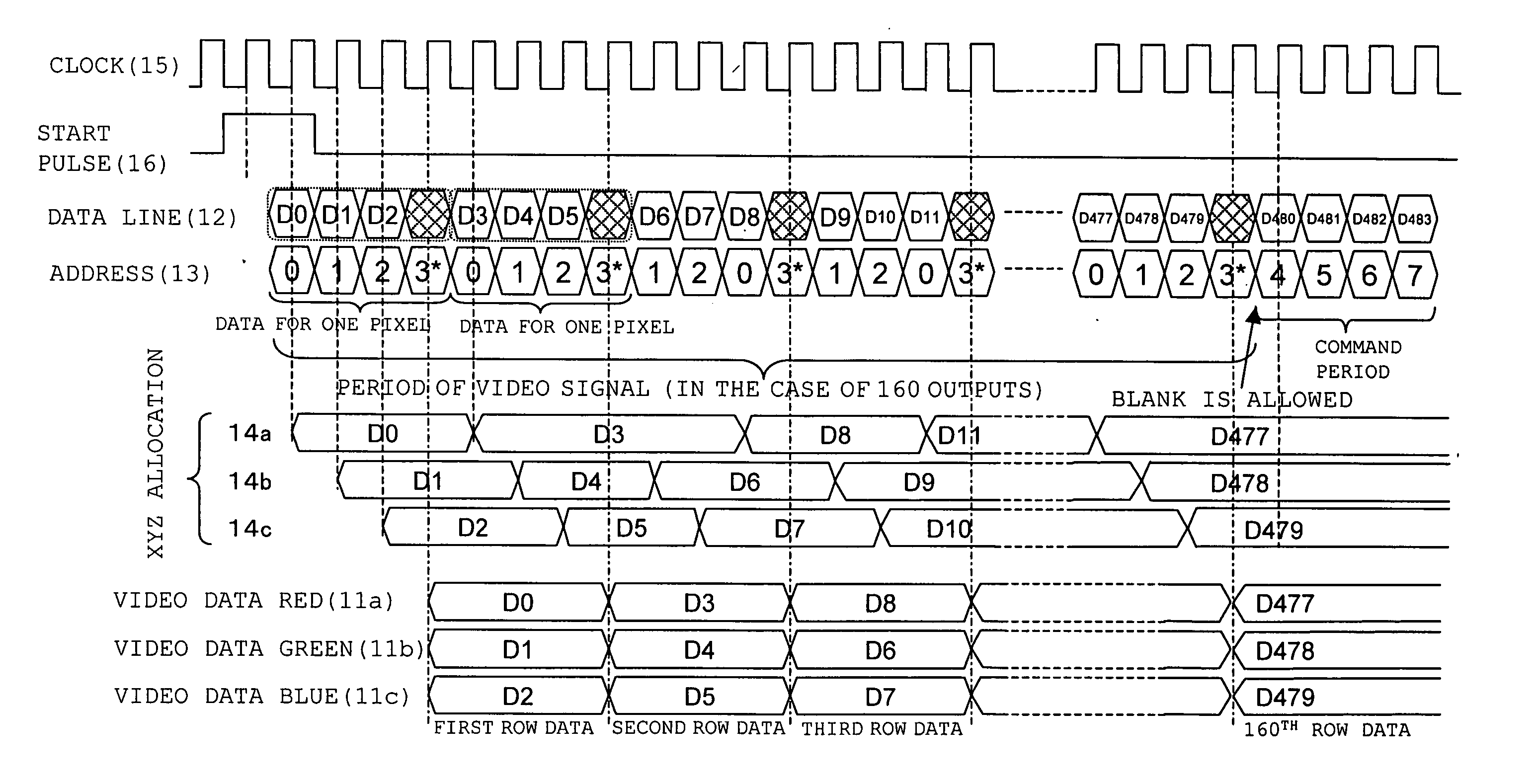
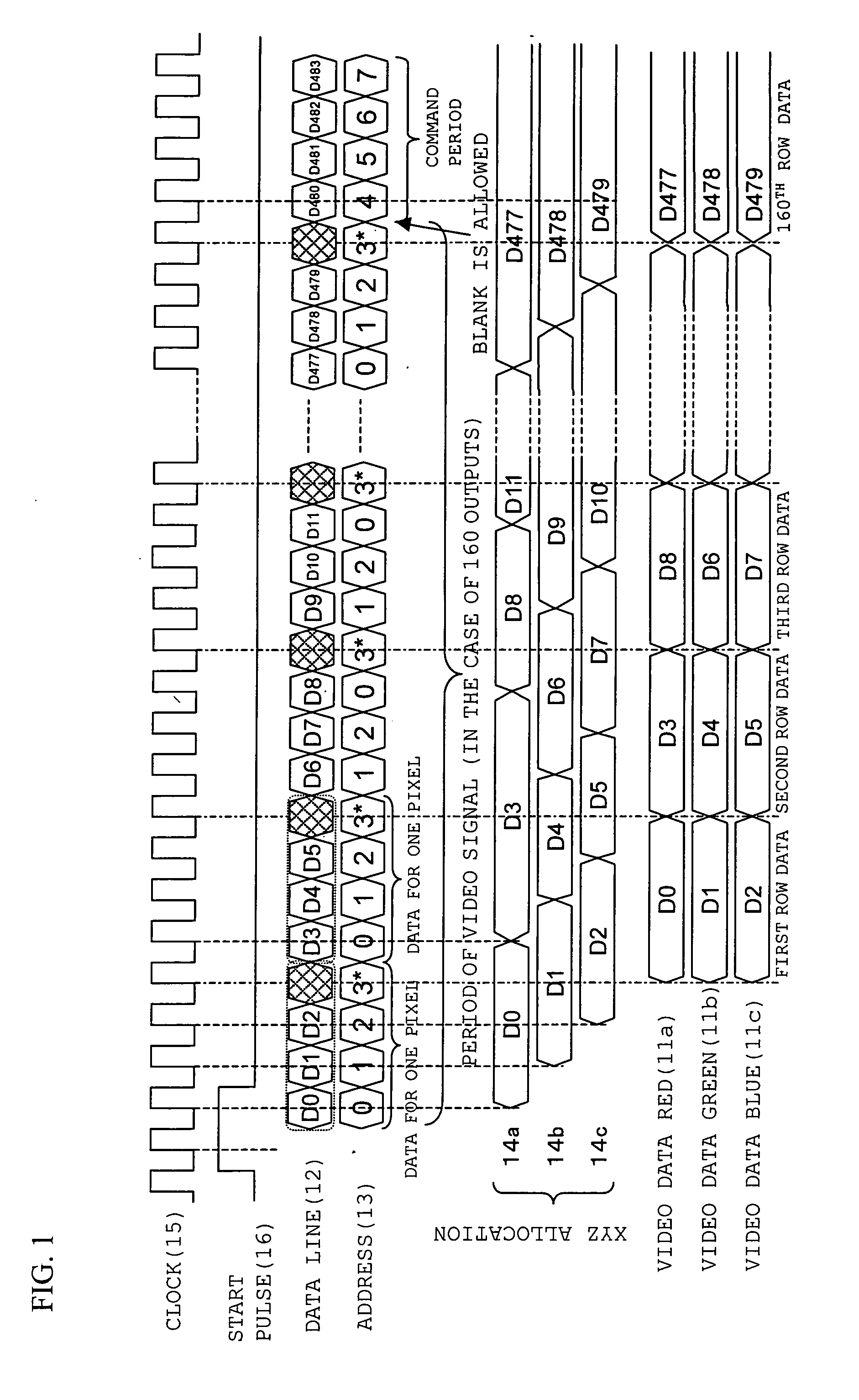
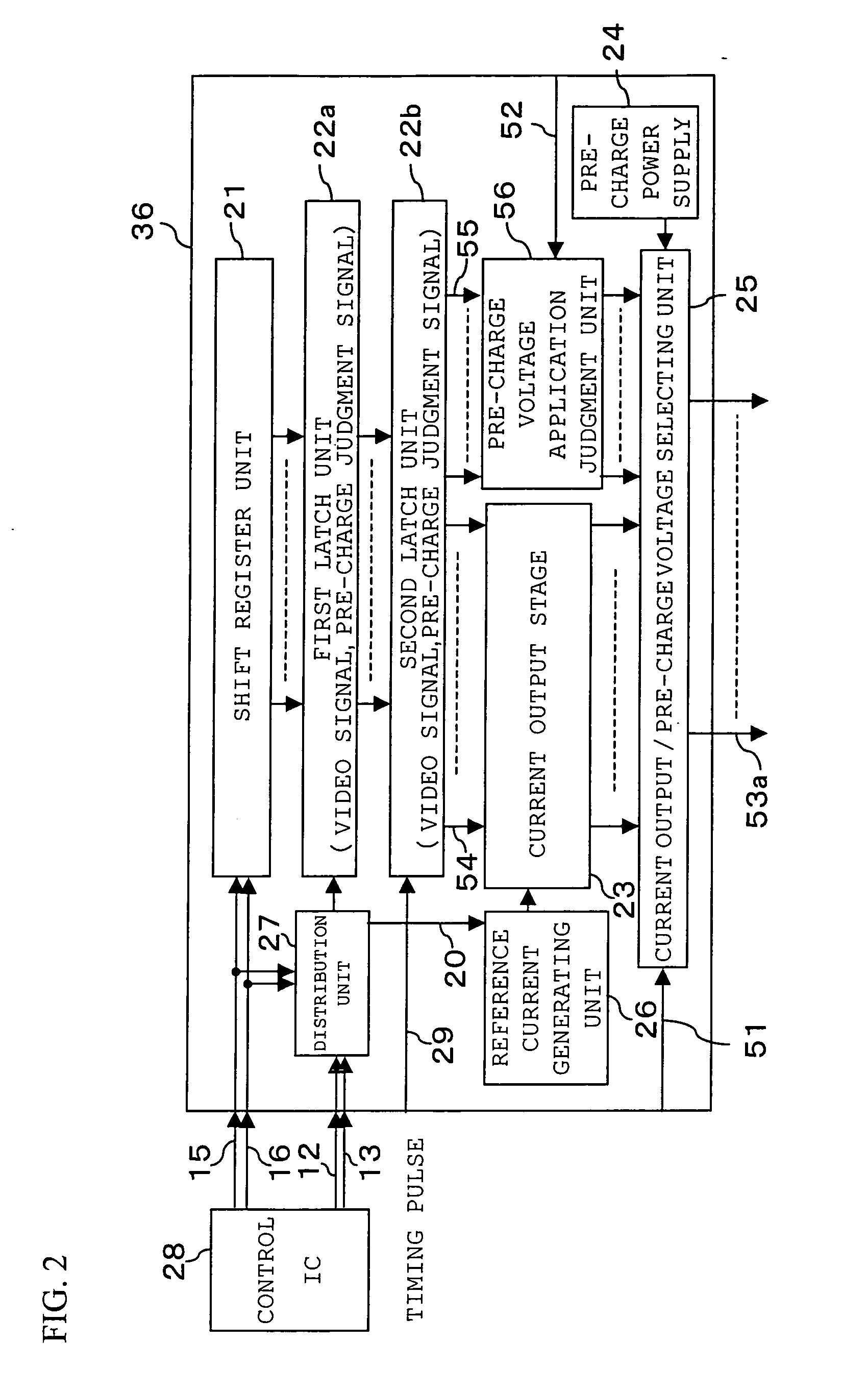
[0216] A structure of a current output type source driver IC 36 in a current output type semiconductor device in embodiment 2 of the present invention is shown in FIG. 2. Since the number of outputs can be realized simply by increasing and reducing the numbers of shift registers 21, latch units 22, current output stages 23, pre-charge voltage application judgment units 56, and current output / pre-charge voltage selection units 25, which are required for one output, according to an increase and a decrease of the number of outputs, it is possible to cope with an arbitrary number of outputs. However, if the number of outputs increases, since a chip size becomes too large and general versatility is lost, about 600 is the maximum practically.

[0217] A video signal of the driver IC 36 of the invention is inputted from a control IC 28 through signal lines 12 and 13. This video signal is distributed into a video signal and various setting signals by a distribution unit 27, and only the video...


PUM


Abstract

To provide a current output type semiconductor circuit, a drive device for display, a display device, and a current output method that can control an increase in a circuit size to be lower even if the number of output bits of a current driver is increased.
A current output type semiconductor circuit, including first current source groups 241a and 241b, includes first unit transistors of outputting a predetermined current and output lower order N (N is a natural number) bits; and second current source groups 242a, 242b, 242c, 242d, 242e, and 242f that include second unit transistors of outputting a current larger than that of the first unit transistors and output higher order M (M is a natural number, (N+M)≧3) bits.

Description

TECHNICAL FIELD [0001] The present invention relates to a driving semiconductor circuit of performing current output which is used for a display device of performing gradation display according to an amount of current such as an organic field luminous element. BACKGROUND ART [0002] An organic luminous element is hopeful for a display device of the next generation, because the organic luminous element is a self-luminous element, and therefore, for example, the device does not require a backlight required in a liquid crystal display device, and has a wide viewing angle. [0003] A sectional view of an element structure of a general organic luminous element is shown in FIG. 4. The organic luminous element has a structure in which an organic layer 42 is sandwiched by a cathode 41 and an anode 43. When a DC power supply 44 is connected to this organic luminous element, holes and electrons are injected into the organic layer 42 from the anode 43 and the cathode 41, respectively. The injecte...

Claims


Application Information

Patent Timeline
Patent Type & Authority Applications(United States)
IPC IPC(8): H02P9/00H03M1/68H03M1/74
CPCG09G3/006H03M1/745G09G3/32G09G3/325G09G3/3283G09G2300/0819G09G2300/0842G09G2310/0251G09G2310/027G09G2310/08G09G2320/0223G09G2320/0276G09G2320/103G09G2340/0428H03M1/68G09G3/30G09G3/20
Inventor TSUGE, HITOSHI
Owner JAPAN DISPLAY CENTRAL CO LTD
Why Eureka
Try Eureka