
Inductor and magnetic body thereof

a technology of inductor and magnetic body, which is applied in the direction of transformer/inductance magnetic core, core/yokes, instruments, etc., can solve the problems of reducing reducing the inductance and thus the efficiency of inductor, so as to achieve high insulation, withstand a larger dc bias, and high inductance.

Inactive Publication Date: 2006-12-14
DELTA ELECTRONICS INC
View PDF15 Cites 33 Cited by
  • Summary
  • Abstract
  • Description
  • Claims
  • Application Information

AI Technical Summary

Benefits of technology

[0010] In view of the foregoing, the invention is to provide an inductor and the magnetic body thereof. By using the complex magnetic materials and the combination of different particle sizes thereof, the edge effect can be overcome to achieve higher inductance and longer device lifetime.
[0014] As mentioned above, the inductor and the magnetic body thereof of the invention use the mixture of magnetic materials with different particle sizes and a resin to form the magnetic body. Since the complex magnetic materials overcome the possible edge effect or low the inductance due to a unique particle size as in the prior art, the inductor and magnetic body of the invention can therefore achieve a higher inductance and withstand a larger DC bias. Moreover, the resin may be made of nano-inorganic powders with high insulation and high thermal conductivity. In addition to the goals of increasing the DC bias and lower the eddy current loss, the resin deterioration problem of the prior art can be improved because of the increased thermal conductivity. Therefore, the inductor has a longer lifetime.

Problems solved by technology

Since the conventional inductor 1 is composed of individual components, there are, however, many air gaps in the assembled inductor 1.
For example, magnetic powders with a too large average particle size will render an iron core cover that cannot withstand a large DC bias.
On the other hand, if the average particle size of the magnetic powders is too small, the inductance and thus the efficiency of the inductor decrease.
Besides, the thermosetting resin is likely to deteriorate under the heat generated by the inductor 2 in operation.

Method used


Image

  • Inductor and magnetic body thereof
  • Inductor and magnetic body thereof
  • Inductor and magnetic body thereof

Examples


Embodiment Construction

[0020] The present invention will be apparent from the following detailed description, which proceeds with reference to the accompanying drawings, wherein the same references relate to the same elements.

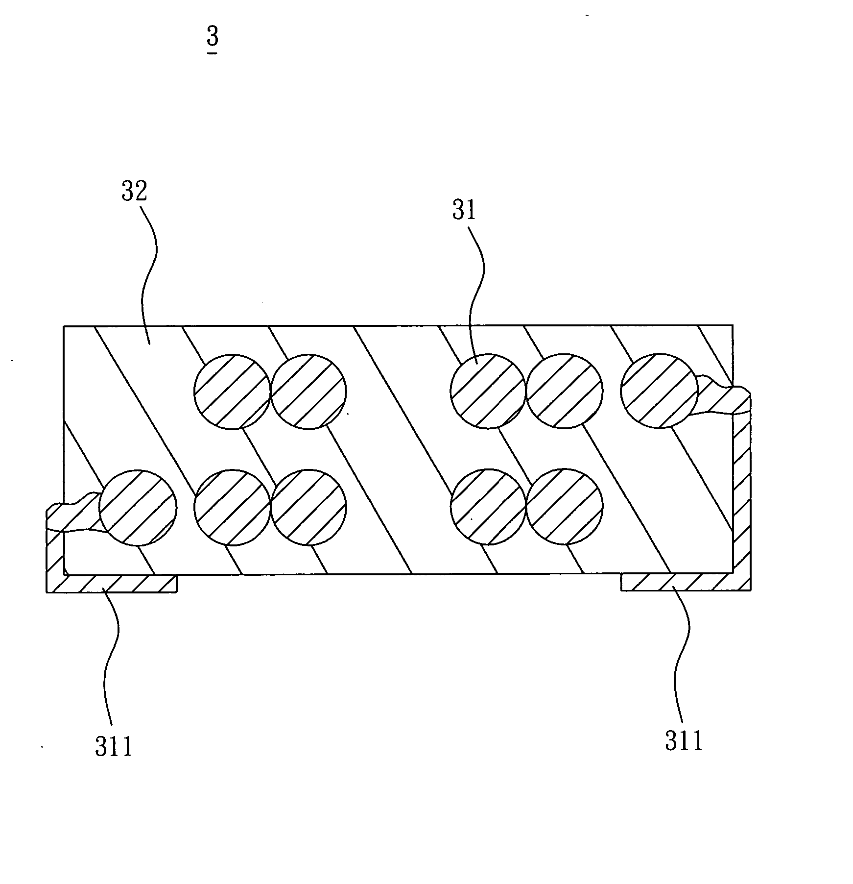
[0021]FIG. 4 shows a schematic cross-sectional view of an inductor 3 used in a transforming device or a regulating device. In the embodiment, the inductor 3 includes a coil 31 and at least a magnetic body 32.

[0022] The magnetic body 32 covers the coil 31. The coil 31 is made from a circular wire, square wire, or flat wire wound several turns. Both ends 311 of the coil 31 are led out of the magnetic body 32 to be the pins of the inductor 3.

[0023] The magnetic body 32 is made by mixing a first magnetic material, a second magnetic material, and a thermosetting resin, and then curing the mixture.

[0024] The average particle size of the first magnetic material ranges from 35 μm to 125 μm. The average particle size of the second magnetic material is smaller than 35 μm. The shape of the ...


PUM

PropertyMeasurementUnit
particle sizeaaaaaaaaaa

Abstract

A magnetic body for a transforming device or a regulating device is formed by mixing a first magnetic material, a second magnetic material and a resin, and curing the mixture. The average particle size of the first magnetic material ranges from 35 μm to 125 μm and the average particle size of the second magnetic material is smaller than 35 μm.

Description

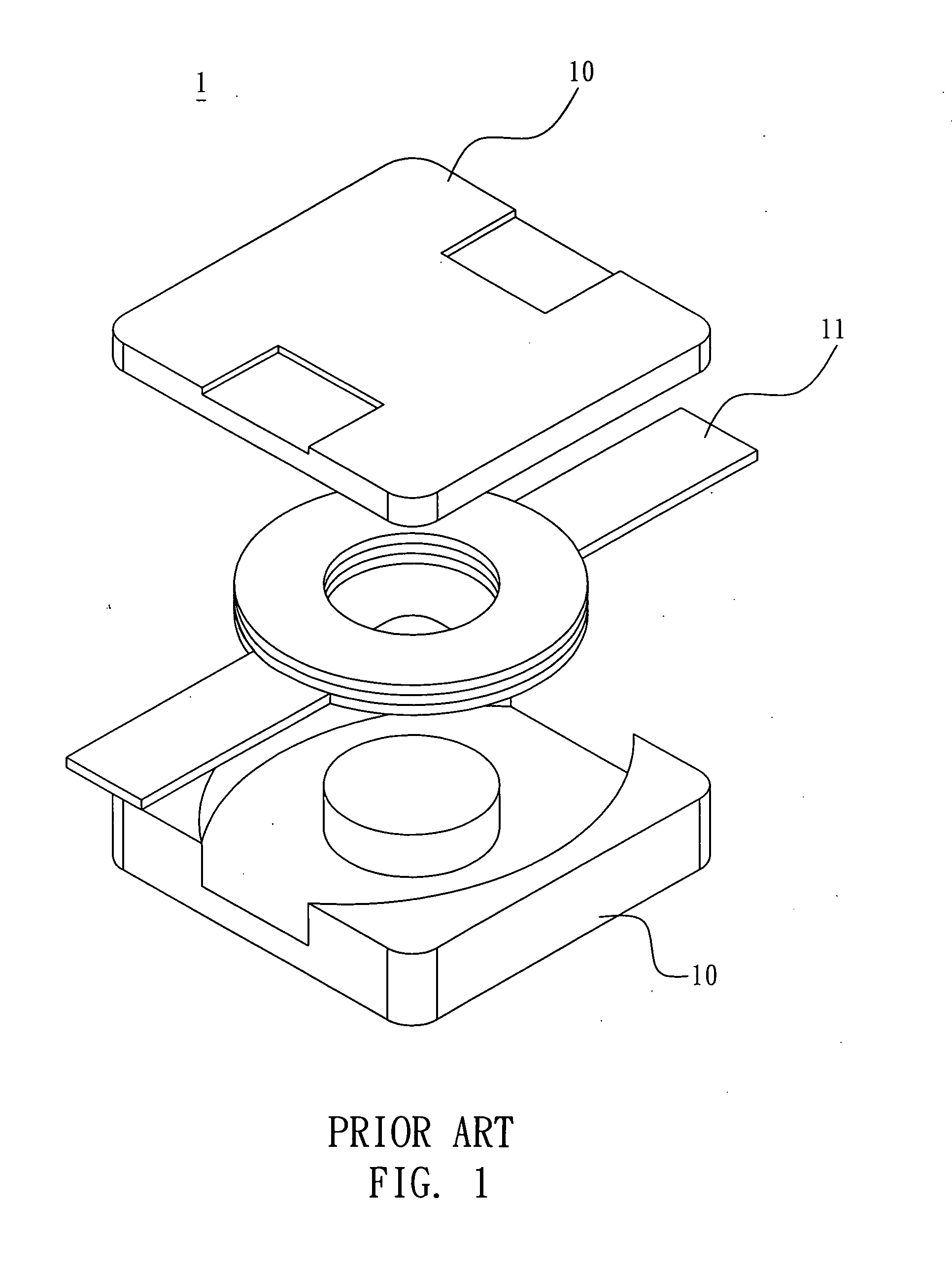
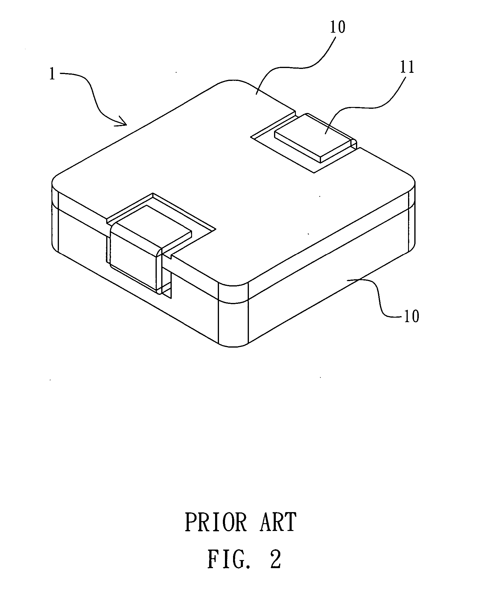
BACKGROUND OF THE INVENTION [0001] 1. Field of Invention [0002] The invention relates to an inductor and the magnetic body thereof. More particularly, the invention relates to a high-efficiency inductor and the magnetic body thereof. [0003] 2. Related Art [0004] In the trend of miniaturizing electronic device, some basic and important elements such as inductors are also required to reduce their volumes and masses. Therefore, it is the current goal to achieve small volumes for the elements while at the same time keeping their low loss and high efficiency properties. [0005] The conventional inductor has an iron core and a coil surrounding the iron core. The iron core can be in the C-shaped, E-shaped, I-shaped, or a toroidal shape. FIG. 1 shows the exploded view of an E / I shaped inductor 1. The coil 11 is located between an E-shaped iron core 10 and an I-shaped iron core 10. The assembled inductor 1 is shown in FIG. 2. Finally, the inductor 1 is used in devices such as a surface mounte...

Claims


Application Information

Patent Timeline
Patent Type & Authority Applications(United States)
IPC IPC(8): H01F17/04G11B5/33
CPCH01F1/26H01F3/08H01F2017/046H01F27/292H01F27/34H01F17/043
Inventor LEE, CHENG-HONGSHIU, MING-SHAN
Owner DELTA ELECTRONICS INC
Learn More