Method and system for cooling heat-generating component in a closed-loop system

a closed-loop cooling and heat-generating component technology, applied in refrigeration components, light and heating equipment, x-ray tubes, etc., can solve the problems of degrading or completely ruining the performance of the heat-generating component, not being able to cool to the desired level, and adding cost and expense to the overall system, so as to facilitate the use of low-cost components, improve the cooling of a heat-generating component, and increase the pressure of the closed-loop system

Inactive Publication Date: 2006-12-14
TARK
View PDF39 Cites 12 Cited by
  • Summary
  • Abstract
  • Description
  • Claims
  • Application Information

AI Technical Summary

Benefits of technology

[0015] What is needed, therefore, is a system and method which facilitates using low-cost components, such as a non-differential pressure switch (rather than a differential pressure switch), which also provides a means for increasing pressure in the closed-loop system.
[0016] It is, therefore, a primary object of the invention to provide a system and method for improving cooling of a heat-generating component, such as an X-ray tube in an X-ray system.

Problems solved by technology

The increase in temperature of the fluid could also result in the heat-generating component not being cooled to the desired level.
This could either degrade or completely ruin the performance of the heat-generating component altogether.
This added cost and expense to the overall system.
Unfortunately, the pressure differential switch of the type used in these types of cooling systems of the past and described earlier herein are expensive and require additional care when coupling to the venturi.
The pressure differential switches of the past were certainly more expensive than a conventional pressure switch which simply monitors a pressure at a given point in a conduit in the closed-loop system.

Method used


Image

  • Method and system for cooling heat-generating component in a closed-loop system
  • Method and system for cooling heat-generating component in a closed-loop system
  • Method and system for cooling heat-generating component in a closed-loop system

Examples


Embodiment Construction

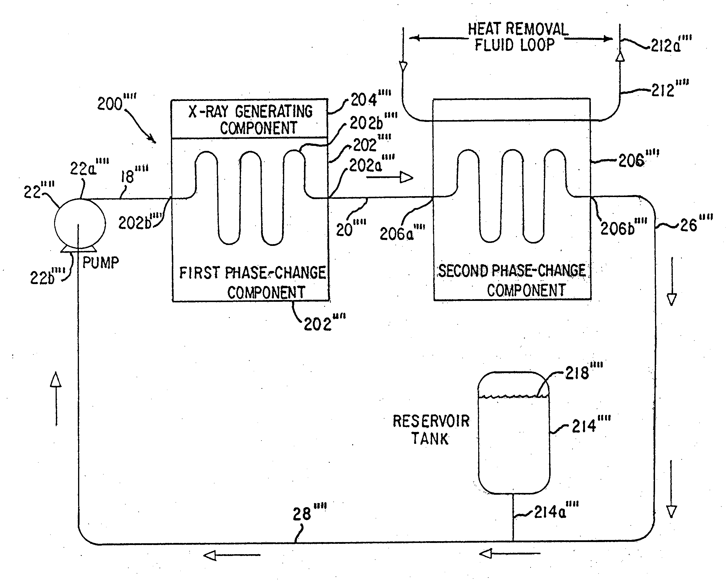
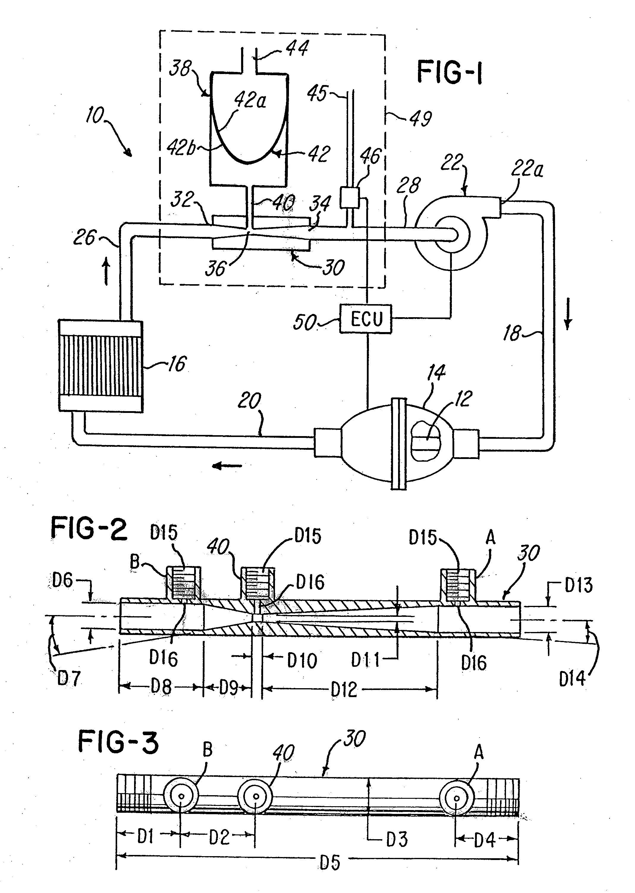
[0039] Referring now to FIG. 1, a cooling system 10 is shown for cooling a component 12. While one embodiment of the invention will be described herein relative to a cooling system for cooling the X-ray tube 12 situated inside a housing 14. It should be appreciated that the features of the invention may be used for cooling any heat-generating component in the closed-loop system 10.

[0040] As mentioned, the cooling system 10 comprises a heat-generating component, such as the X-ray tube 12, and a heat exchanger or heat-rejection component 16, which in the embodiment being described is a heat exchanger available from Lytron of Woburn, Mass.

[0041] The system 10 further comprises a fluid pump 22 which is coupled to housing 14 via conduit 18. In the embodiment being described, the pump 22 pumps fluid, such as a coolant, through the various conduits and components of system 10 in order to cool the components 12. It has been found that one suitable pump 22 is the pump Model No. H0060.2A-11...


PUM


Abstract

A system and method for reducing or eliminating pump cavitation in a closed system having at least one or a plurality of fluid phase changes. The system comprises a venturi having a throat which is coupled to a reservoir tank.

Description

RELATED APPLICATION [0001] This application is a continuation-in-part of U.S. patent application Ser. No. 11 / 302,466 filed Dec. 13, 2005, which is a continuation-in-part of U.S. patent application Ser. No. 10 / 631,179 filed Jul. 31, 2003, which is a continuation-in-part of U.S. patent application Ser. No. 09 / 745,588 filed Dec. 21, 2000, issued as U.S. Pat. No. 6,623,160, all of which are incorporated herein by reference and made a part hereof.BACKGROUND OF THE INVENTION [0002] 1. Field of the Invention [0003] This invention relates to a cooling system, and more particularly, it relates to a closed-loop cooling system to facilitate cooling an x-ray tube using a reservoir situated between an inlet of a pump and phase change component. [0004] 2. Description of the Prior Art [0005] In many prior art cooling systems, the fluid is absorbing heat from a heat-generating component. The fluid is conveyed to a heat exchanger which dissipates the heat and the fluid is then recirculated to the he...

Claims


Application Information

Patent Timeline
Patent Type & Authority Applications(United States)
IPC IPC(8): H01J35/12H01J35/10F25B1/06
CPCF25B1/06F25B23/00F25B2341/0011H05G1/025H01J2235/127H01J2235/1275H05G1/02F25B2500/01
Inventor MCCARTHY, JOSEPH H. JR.
Owner TARK
Why Eureka
Try Eureka