Stent for guiding the location/direction of implant, and production method thereof

Inactive Publication Date: 2006-12-14
MJRAD
View PDF5 Cites 31 Cited by
  • Summary
  • Abstract
  • Description
  • Claims
  • Application Information

AI Technical Summary

Problems solved by technology

If damage to the root of an adjacent tooth occurs due to an implant being inserted in a wrong location, the damaged adjacent tooth must be undesirably removed.
Therefore, there is a probability of error occurring.
As well, in the substantial implant operation, errors may also occur.
Thus, the accuracy of the manufactured plastic rapid prototyping model is r

Method used


Image

  • Stent for guiding the location/direction of implant, and production method thereof
  • Stent for guiding the location/direction of implant, and production method thereof
  • Stent for guiding the location/direction of implant, and production method thereof

Examples


Embodiment Construction

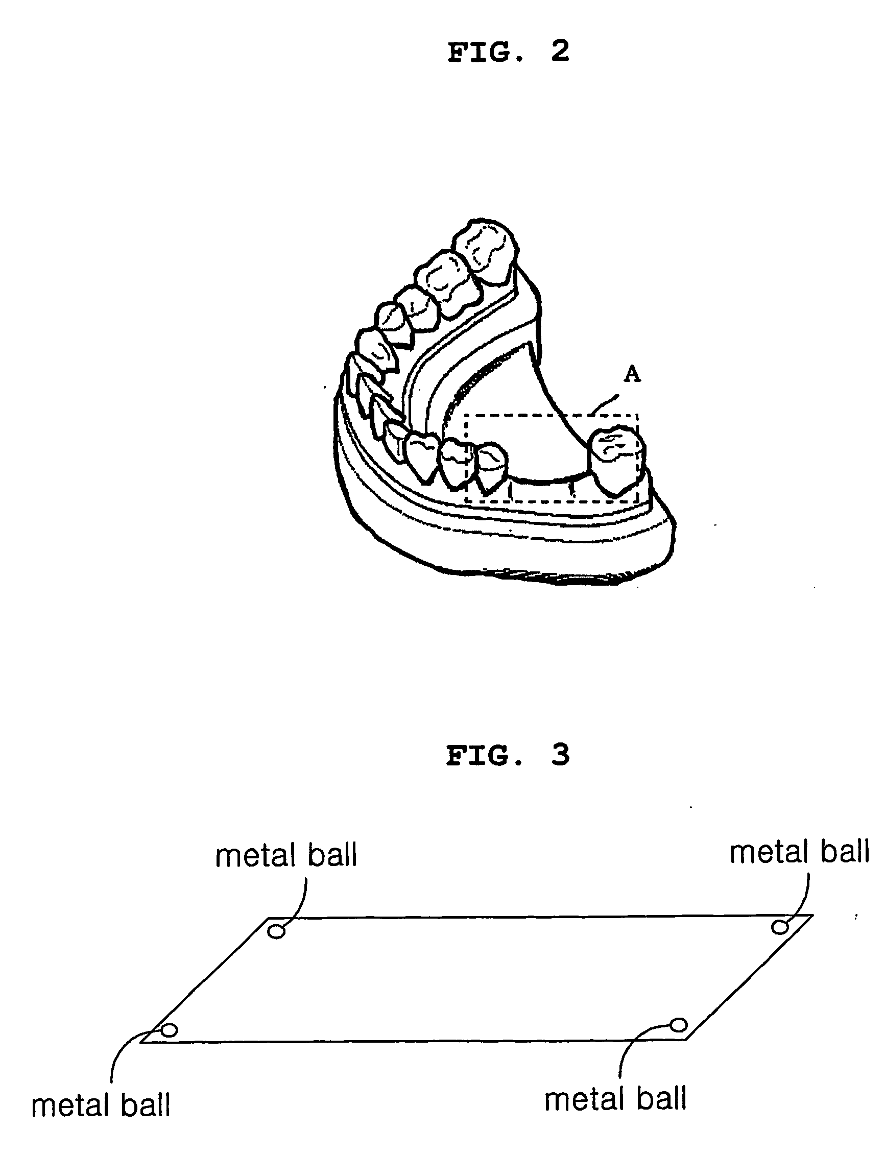
[0030] A principle of the present invention is that a mouth model having the same shape as a patient's mouth structure is provided by using a dental plastic replica, thus reducing production costs, and preventing an error from occurring during a dental implant operation. Furthermore, the present invention is provided the precise location and direction of a guide hole by using a plastic plate including three or four metal balls. In an explanation of the metal balls, the number of the metal balls will be described as three or more, three or four, or four. That is, the plastic plate includes at least three metal balls.

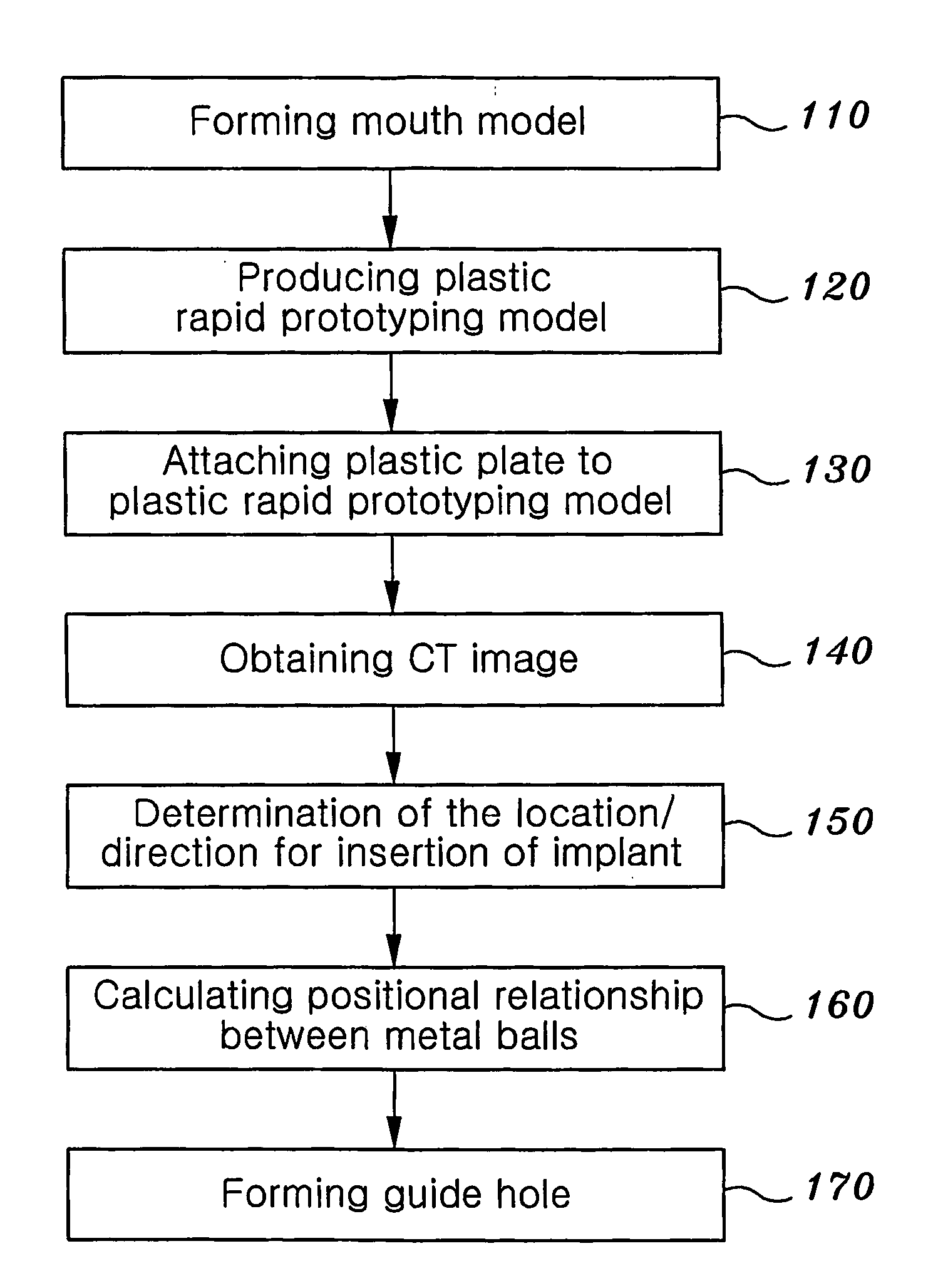
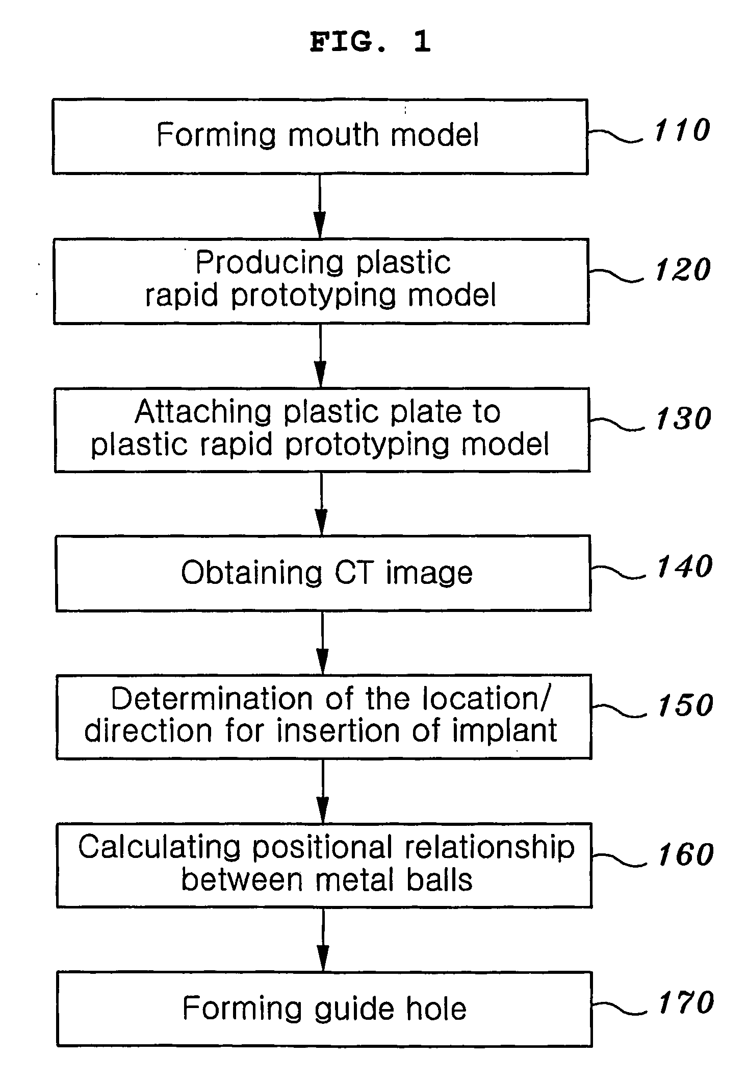
[0031]FIG. 1 is a flow chart showing a method of producing a stent, according to an embodiment of the present invention.

[0032] Hereafter, the present invention will be explained with reference to FIG. 1.

[0033] At step 110, a mouth model is formed. The mouth model is made of a dental plastic replica. A plaster cast modeling the mouth including a region for an implant in...


PUM


Abstract

The present invention is disclosed a stent for guiding the location/direction for the insertion of an implant a production method thereof. The method includes the steps of forming a plaster cast modeling of a mouth state using a plastic replica; and manufacturing a plastic cast model having an occlusal surface of the location for the insertion of the implant using the plaster cast; fastening a plastic plate having on corners thereof a plurality of metal balls to an upper end of the plastic cast model; and obtaining computed tomographic (CT) image of the mouth after placing the plastic cast model, on which the plastic plate is fastened, in the mouth, and forming a hole in a predetermined position in the stent to correspond to both a location and a direction of inserting the implant determined by a dentist based on the CT image.

Description

TECHNICAL FIELD [0001] The present invention relates, in general, to devices for guiding the installation of implants and production methods thereof and, more particularly, to a guide model used for the insertion of an implant and a method of producing a stent for guiding the location and direction for the insertion of an implant as determined by a dentist. BACKGROUND ART [0002] Generally, in a dental implant operation to fill a region of a mouth where a patient is missing a tooth, it is important to insert that the implant is installed at a stable and precise location and angle and to a precise depth. If damage to the root of an adjacent tooth occurs due to an implant being inserted in a wrong location, the damaged adjacent tooth must be undesirably removed. In particular, the insertion of the implant must avoid anatomic structures, such as nervous tissue of a lower jaw and a maxillary sinus of an upper jaw or a lower jaw Therefore, before the dental implant operation is executed, ...

Claims


Application Information

Patent Timeline
IPC IPC(8): A61C3/00A61C1/08A61C13/00
CPCA61C13/0004A61C1/084
Inventor HEO, JUN-SEOK
Owner MJRAD
Why Eureka
Try Eureka