Method and apparatus for adjusting feature size and position

a technology of feature size and position, applied in the field of masking techniques, can solve the problems of reducing the reducing the minimum pitch of a particular photolithographic technique, and reducing the size of features

Inactive Publication Date: 2006-12-14
ROUND ROCK RES LLC
View PDF99 Cites 343 Cited by
  • Summary
  • Abstract
  • Description
  • Claims
  • Application Information

AI Technical Summary

Benefits of technology

[0017] According to another aspect of the invention, a method is provided for processing a semiconductor substrate. The method comprises selecting a photolithographic system to define features in a photoresist layer. The photolithographic system has a minimum definable feature size and a critical dimension of the features is more than about 150% of the minimum definable feature size. The features in the photoresist layer are defined using the photolithographic system. A pattern formed by the features is transferred to an underlying layer to form a plurality of mandrels. Spacers are formed on sidewalls of the mandrels and the mandrels are preferentially removed relative to the spacers.

Problems solved by technology

However, due to factors such as optics and light or radiation wavelength, photolithography techniques each have a resolution limit that results in a minimum pitch below which a particular photolithographic technique cannot reliably form features.
Thus, the minimum pitch of a photolithographic technique is an obstacle to continued feature size reduction.

Method used


Image

  • Method and apparatus for adjusting feature size and position
  • Method and apparatus for adjusting feature size and position
  • Method and apparatus for adjusting feature size and position

Examples


Embodiment Construction

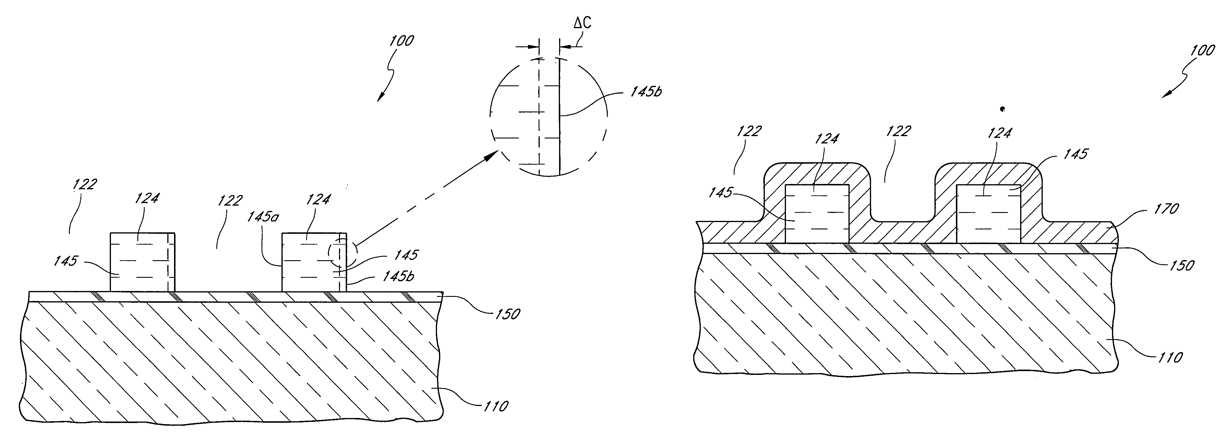
[0045] Due to the continuing trend to decrease feature sizes, lower wavelength photolithographic techniques may be used to pattern photoresist to define features used in pitch multiplication. In addition, these techniques may be pushed near their resolution limits to form ever smaller features, such as the mandrels used in pitch multiplication. At the resolution limits, however, the margins of error for forming features of a desired, or target, size increase; variations in the critical dimensions of features formed by photolithography increase as the resolution limits are approached. For example, 100 nm features can be formed with a variation of about ±15 nm, 200 nm features with a variation of about ±10 nm and 300 nm features with a variation of about ±7 nm. The larger margins of error in photoresist feature sizes lead to larger variations in mandrel size. As a result, the above-described problems with pitch regularity are exacerbated by attempts to define ever smaller features by ...


PUM


Abstract

Variations in the pitch of features formed using pitch multiplication are minimized by separately forming at least two sets of spacers. Mandrels are formed and the positions of their sidewalls are measured. A first set of spacers is formed on the sideswalls. The critical dimension of the spacers is selected based upon the sidewall positions, so that the spacers are centered at desired positions. The mandrels are removed and the spacers are used as mandrels for a subsequent spacer formation. A second material is then deposited on the first set of spacers, with the critical dimensions of the second set of spacers chosen so that these spacers are also centered at their desired positions. The first set of spacers is removed and the second set is used as a mask for etching a substrate. By selecting the critical dimensions of spacers based partly on the measured position of mandrels, the pitch of the spacers can be finely controlled.

Description

REFERENCE TO RELATED APPLICATIONS [0001] This application is related to the following: U.S. patent application Ser. No. 10 / 934,778 to Abatchev et al., filed Sep. 2, 2004; and U.S. Patent Provisional Application No. 60 / 662,323 to Tran et al., filed Mar. 15, 2005, entitled Pitch Reduced Patterns Relative To Photolithography Features, Attorney Docket No. MICRON.316PR (Micron Ref. No. 2004-1130.00 / US).BACKGROUND OF THE INVENTION [0002] 1. Field of the Invention [0003] This invention relates generally to integrated circuit fabrication and, more particularly, to masking techniques. [0004] 2. Description of the Related Art [0005] As a consequence of many factors, including demand for increased portability, computing power, memory capacity and energy efficiency, integrated circuits are continuously being reduced in size. The sizes of the constituent features that form the integrated circuits, e.g., electrical devices and interconnect lines, are also constantly being decreased to facilitate ...

Claims


Application Information

Patent Timeline
Patent Type & Authority Applications(United States)
IPC IPC(8): H01L21/4763H01L21/336
CPCH01L21/0337H01L21/0338H01L21/31144Y10S438/946H01L27/105Y10S438/947H01L21/76838
Inventor WELLS, DAVID H.
Owner ROUND ROCK RES LLC
Why Eureka
Try Eureka