Devices and methods for forming magnetic anastomoses between vessels

a technology of magnetic anastomosis and a device, which is applied in the direction of magnetic bodies, blood vessels, surgical staples, etc., can solve the problems of increasing the difficulty of sutured anastomosis, high technical and time-consuming, and the inability to form a sutured anastomosis

Inactive Publication Date: 2006-12-14
MEDTRONIC INC
View PDF6 Cites 144 Cited by
  • Summary
  • Abstract
  • Description
  • Claims
  • Application Information

AI Technical Summary

Benefits of technology

[0016] According to still another embodiment, a method for checking a seal between an anastomotic component and a blood vessel to which the anastomotic component is secured is provided. This method includes steps of providing an anastomotic component capable of producing or being attracted by a magnetic field, the anastomotic component having an opening, attaching the anastomotic component to a blood vessel in fluid communication with the lumen of the blood

Problems solved by technology

Despite the considerable advances that have been realized in cardiology and cardiovascular surgery, heart disease remains the leading cause of death throughout much of the world.
The most challenging aspect of CABG (as well as many other procedures that requiring forming an anastomosis) is connecting the graft vessel to the target vessel in a secure, fluid-tight manner.
The small diameter of coronary vessels (typically 1 mm to 4 mm) makes creating these handsewn anastomoses highly technical and time consuming.
The difficulty in forming the sutured anastomosis is exacerbated when access to the target vessel is restricted or limit

Method used


Image

  • Devices and methods for forming magnetic anastomoses between vessels
  • Devices and methods for forming magnetic anastomoses between vessels
  • Devices and methods for forming magnetic anastomoses between vessels

Examples


Embodiment Construction

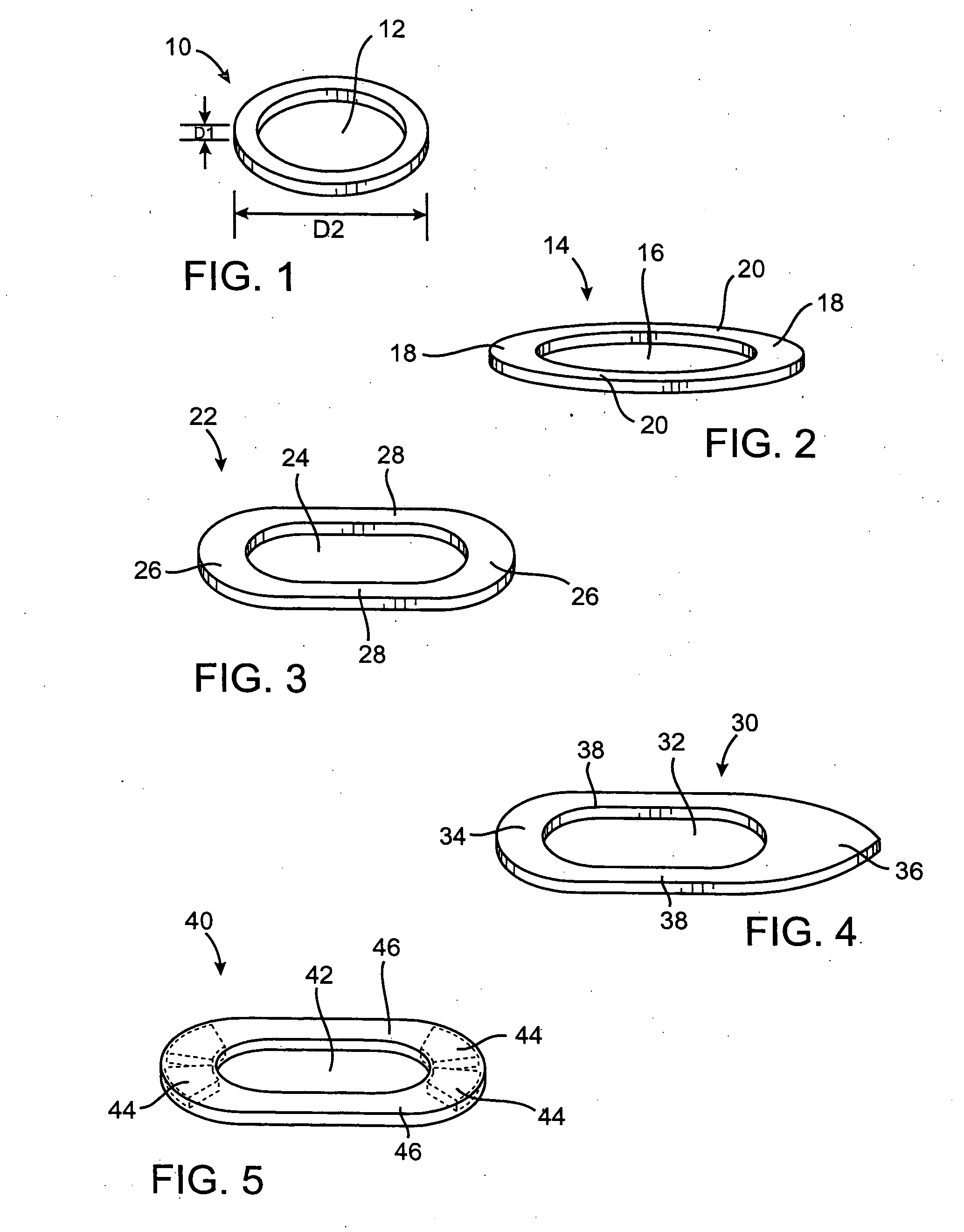
[0166]FIGS. 1-5 illustrate several exemplary embodiments of anastomotic securing components constructed according to the invention for use in forming an anastomosis between first and second hollow bodies. FIG. 1 shows a securing component 10 with an annular body and an opening 12 defined by the body. The component 10 is generally plate-shaped and circular in plan view with a constant (or substantially constant) thickness and width around its perimeter. The securing component 10 is sized and configured to be placed adjacent an opening of a first hollow body that has been prepared for anastomosis to a second hollow body. A second securing component would be placed adjacent an opening of the second hollow body for making the anastomotic connection.

[0167]FIG. 2 shows an elliptical anastomotic securing component 14 with an opening 16. The securing component 14 is generally plate-shaped and the opening 16 is configured to provide the securing component 14 with larger end portions 18 than...


PUM


Abstract

An anastomosis device has first and second components which each having first and second parts. The first and second components are magnetically attracted to one another. The device forms a throughhole when in use. The first parts of the first and second components are positioned radially outward from the second parts relative to the longitudinal axis with the first parts of the first and second components contacting one another and being magnetically attracted to one another. The second parts of the first and second components also being magnetically attracted to one another and are separated by the vessel walls.

Description

CROSS-REFERENCE TO RELATED APPLICATIONS [0001] The present application is a continuation-in-part of application Ser. No. 09 / 915,226, filed Jul. 23, 2001, which is a continuation-in-part of application Ser. No. 09 / 638,805, filed Aug. 12, 2000, which is a continuation-in-part of application Ser. No. 09 / 562,599, filed Apr. 29, 2000. This application also claims priority from provisional application Ser. No. 60 / 255,635, filed Dec. 13, 2000, application Ser. No. 09 / 851,400, filed May 7, 2001 and PCT application no. PCT / US02 / 29485, filed Sep. 16, 2002. The entire disclosure of each of the above-referenced patent applications is expressly incorporated herein by reference.BACKGROUND OF THE INVENTION [0002] 1. Field of the Invention [0003] The invention relates to forming anastomoses between hollow anatomical bodies, such as blood vessels. More particularly, the invention relates to using magnetic force to form anastomoses between such vessels while attempting to minimize the amount of mater...

Claims


Application Information

Patent Timeline
IPC IPC(8): A61B17/08
CPCA61B17/00491H01F7/0242A61B17/0469A61B17/064A61B17/0643A61B17/0644A61B17/068A61B17/11A61B2017/00252A61B2017/00575A61B2017/00592A61B2017/00606A61B2017/00876A61B2017/1107A61B2017/1135A61B2017/1139A61F2/064A61F2002/30079A61F2210/009A61B17/0057
Inventor COLE, DAVID H.GITTINGS, DARIN C.OLSON, STEPHEN L.CARSON, DEAN F.REO, MICHAEL L.LEPULU, KEKESHARKAWY, A. ADAM
Owner MEDTRONIC INC
Why Eureka
Try Eureka