Prosthetic device utilizing electric vacuum pump

a vacuum pump and prosthetic technology, applied in the field of prosthetic limbs, can solve the problems of heavy pump, inability to remove, and difficulty in securing an artificial limb, and achieve the effects of convenient incorporation, convenient use, and convenient incorporation into a prosthetic limb

Active Publication Date: 2006-12-14
WILLOWWOOD GLOBAL LLC
View PDF22 Cites 62 Cited by
  • Summary
  • Abstract
  • Description
  • Claims
  • Application Information

AI Technical Summary

Benefits of technology

[0009] The present invention improves upon the available known prosthetic technology by providing an artificial limb with an electrically activated pump that may be readily incorporated into the artificial limb. Because the electrically activated pump does not require manual manipulation to create vacuum, it is substantially easier to use than a manual pump. Due to the small size and small battery required by the electrically activated pump disclosed here, it may be readily incorporated into a prosthesis.

Problems solved by technology

Artificial limbs have been in use throughout history, having been first recorded circa 2750 B.C. During that period of time, interfacing and suspending an artificial limb has been a continuing challenge.
Creating a reliable sub atmospheric pressure chamber between the residual limb and prosthetic device has, however, proved to be a challenge.
However, the problem with this method is that the pump is heavy, and cannot be removed even in the case of a pump failure.
Furthermore, the pump requires a certain minimum space between the user's limb and prosthetic foot, which may be more than is available if the patient has a relatively long residual limb.
This prohibits the use of this technology for many artificial limb users.
Another disadvantage of this system is that it requires a number of weight activated strokes before the sub atmospheric pressure pump linkage system becomes effective.
It is also awkward to use for many individuals and requires a certain amount of dexterity and strength to operate.
This is a common problem for elderly individuals.

Method used


Image

  • Prosthetic device utilizing electric vacuum pump
  • Prosthetic device utilizing electric vacuum pump
  • Prosthetic device utilizing electric vacuum pump

Examples


Embodiment Construction

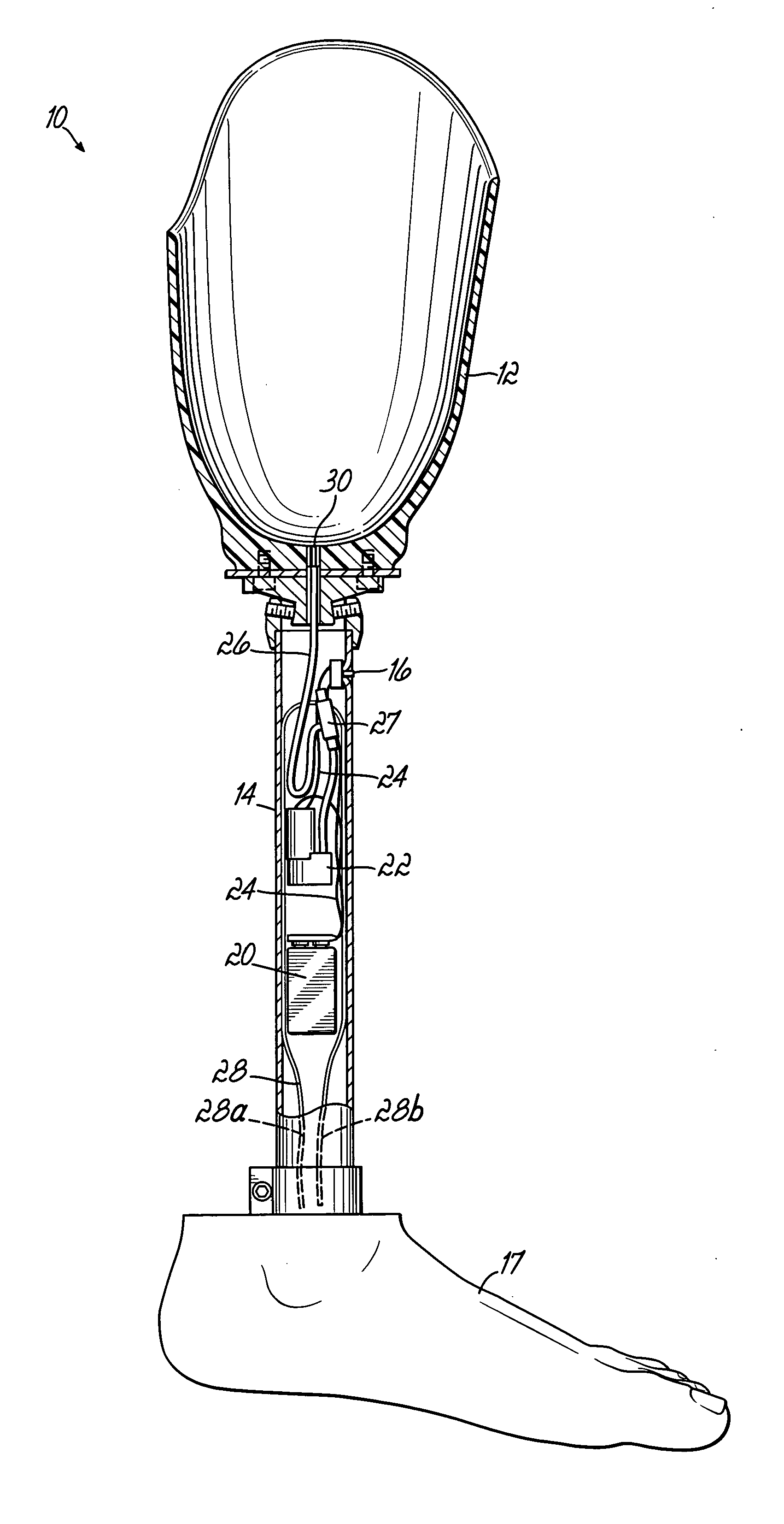
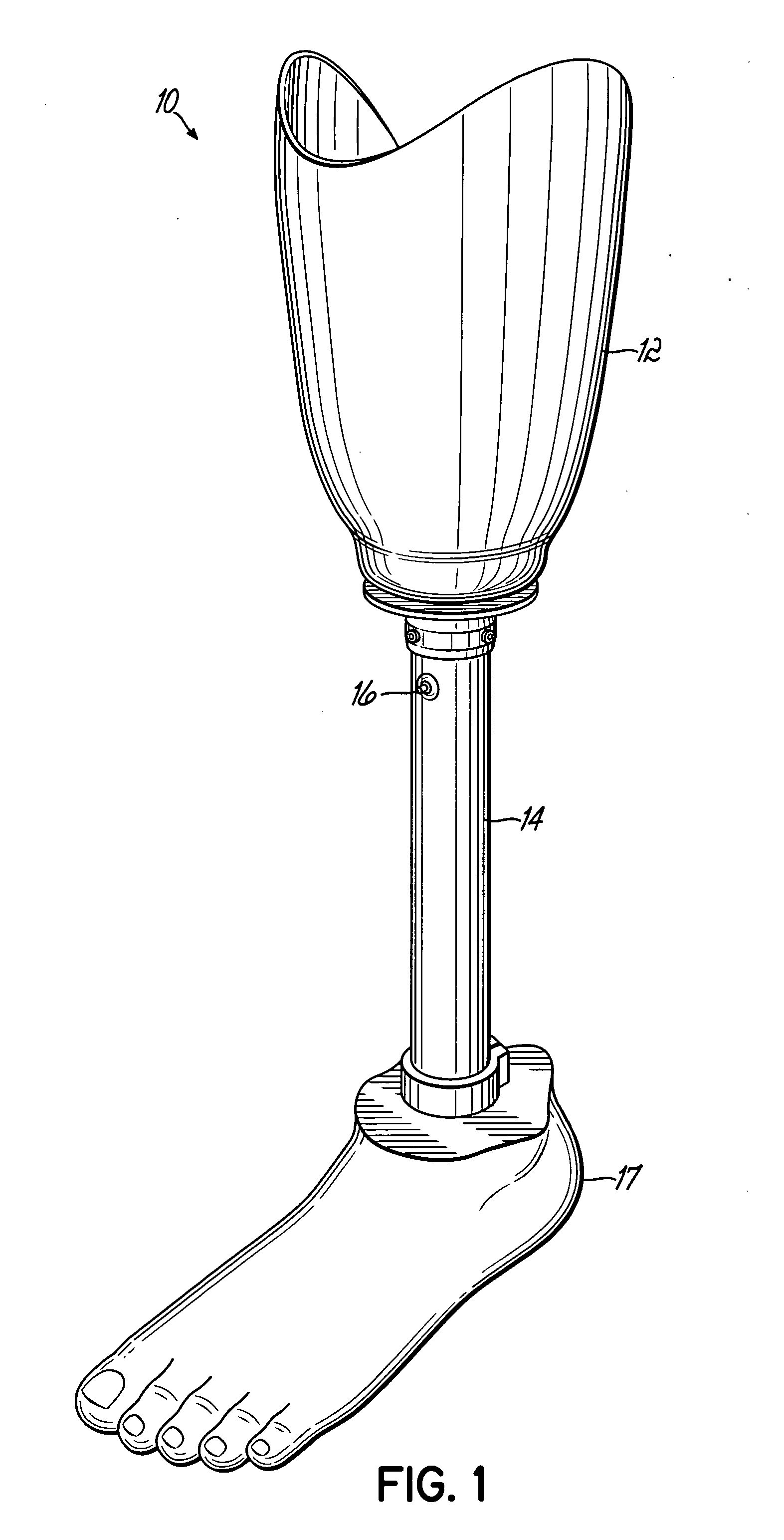
[0018]FIG. 1 illustrates a prosthesis 10 in accordance with principles of the present invention. The prosthesis includes a socket 12 for receiving the patient's residual limb, a column 14, typically a cylindrical section of lightweight metal such as aluminum, and an artificial foot 17. As can be seen on FIG. 1, column 14 includes a vacuum actuator button 16 used to actuate an electric vacuum pump within the column, to draw air from the socket 12 to draw the residual limb into intimate contact with socket 12.

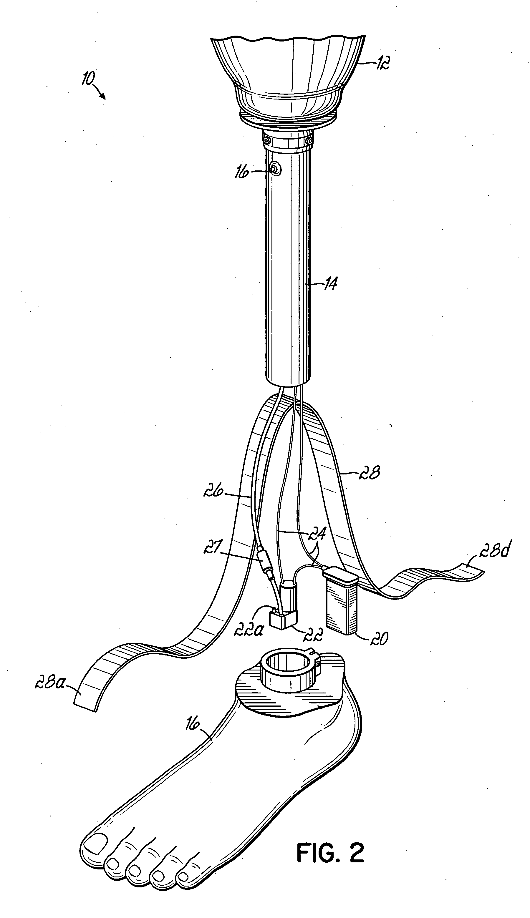
[0019]FIG. 2 illustrates the prosthesis of FIG. 1 disassembled to show the component parts within post 14. Internal to post 14 is a battery 20, such as a conventional 9-volt battery, a vacuum pump 22, and electrical lines 24 for delivering electrical power from battery 20 to vacuum pump 22, and vacuum line 26 for drawing vacuum from socket 12 through a check valve 27. Components 20, 22, 24, 26 and 27 are inserted into post 14 after insertion of a ribbon 28, so that ribbon 28 may...


PUM


Abstract

An artificial limb using a vacuum attachment principle is provided with an electrically activated pump that may be readily incorporated into the artificial limb or into a separate portable device. Because the electrically activated pump does not require manual manipulation to create vacuum, it is substantially easier to use than a manual pump. Due to the small size and small battery required by the electrically activated pump disclosed here, it may be readily incorporated into a prosthesis.

Description

FIELD OF THE INVENTION [0001] The present invention relates to prosthetic limbs. BACKGROUND OF THE INVENTION [0002] Artificial limbs have been in use throughout history, having been first recorded circa 2750 B.C. During that period of time, interfacing and suspending an artificial limb has been a continuing challenge. Various and numerous theories and anatomical constructs have been used over time in an evolving manner, and these have revealed a number of key factors in maximizing comfort and functional potential for persons who wear artificial limbs. [0003] Firstly, the surgical procedure used to perform limb amputation is an important factor. The size and shaping of the patient's residual limb is often important to the comfort the patient will later have with a prosthesis. Stated simply, it is critical that the residual limb and prosthesis interface tightly and couple and distribute pressure evenly across the surface of the residual limb. [0004] Early versions of artificial limbs ...

Claims


Application Information

Patent Timeline
Patent Type & Authority Applications(United States)
IPC IPC(8): A61F2/70A61F2/80A61F2/74
CPCA61F2/68A61F2/76A61F2/80A61F2002/30359A61F2002/30433A61F2002/607A61F2220/0041A61F2002/701A61F2002/742A61F2002/748A61F2002/802A61F2220/0033A61F2002/6614A61F2/5044A61F2/54A61F2/60A61F2/70A61F2002/5032A61F2002/704A61F2002/705A61F2002/7635A61F2002/764A61F2002/805A61F2/74A61F2/742A61F2/748A61B5/1118A61B5/112
Inventor HAINES, WILBUR A.
Owner WILLOWWOOD GLOBAL LLC
Why Eureka
Try Eureka