Method and apparatus for monitoring physical network topology information

a physical network topology and information technology, applied in the field of network cable management, can solve the problems that exemplary approaches have not been sufficient to meet the needs of network managers for accurate physical network topology information, and achieve the effects of improving reliability, reducing cabling complexity, and improving real-time reporting of patch panel connectivity

Inactive Publication Date: 2006-12-14
PANDUIT
View PDF99 Cites 139 Cited by
  • Summary
  • Abstract
  • Description
  • Claims
  • Application Information

AI Technical Summary

Benefits of technology

[0006] A method and apparatus are provided for monitoring the physical topology of a network on a real-time basis. For patch panel systems, in one embodiment, a distributed architecture may be used that allows each patch panel to determine port level connectivity independently. Improved real-time reporting of patch panel connectivity may be provided with reduced cabling complexity, increased reliability, and decreased maintenance costs. Further, the physical equipment and / or physical location information associated with patch panel ports connected by a patch cord may be determined as each respective patch cord connection is made, thereby providing physical network topology information, or network path information, associated with the respective patch cord connections in real-time. In addition, this embodiment is compatible with (i.e., may communicate with and be controlled by) a multipurpose network management system (NMS).

Problems solved by technology

Unfortunately, such exemplary approaches have proven inadequate to meet the need of network managers for accurate physical network topology information.

Method used


Image

  • Method and apparatus for monitoring physical network topology information
  • Method and apparatus for monitoring physical network topology information
  • Method and apparatus for monitoring physical network topology information

Examples


Embodiment Construction

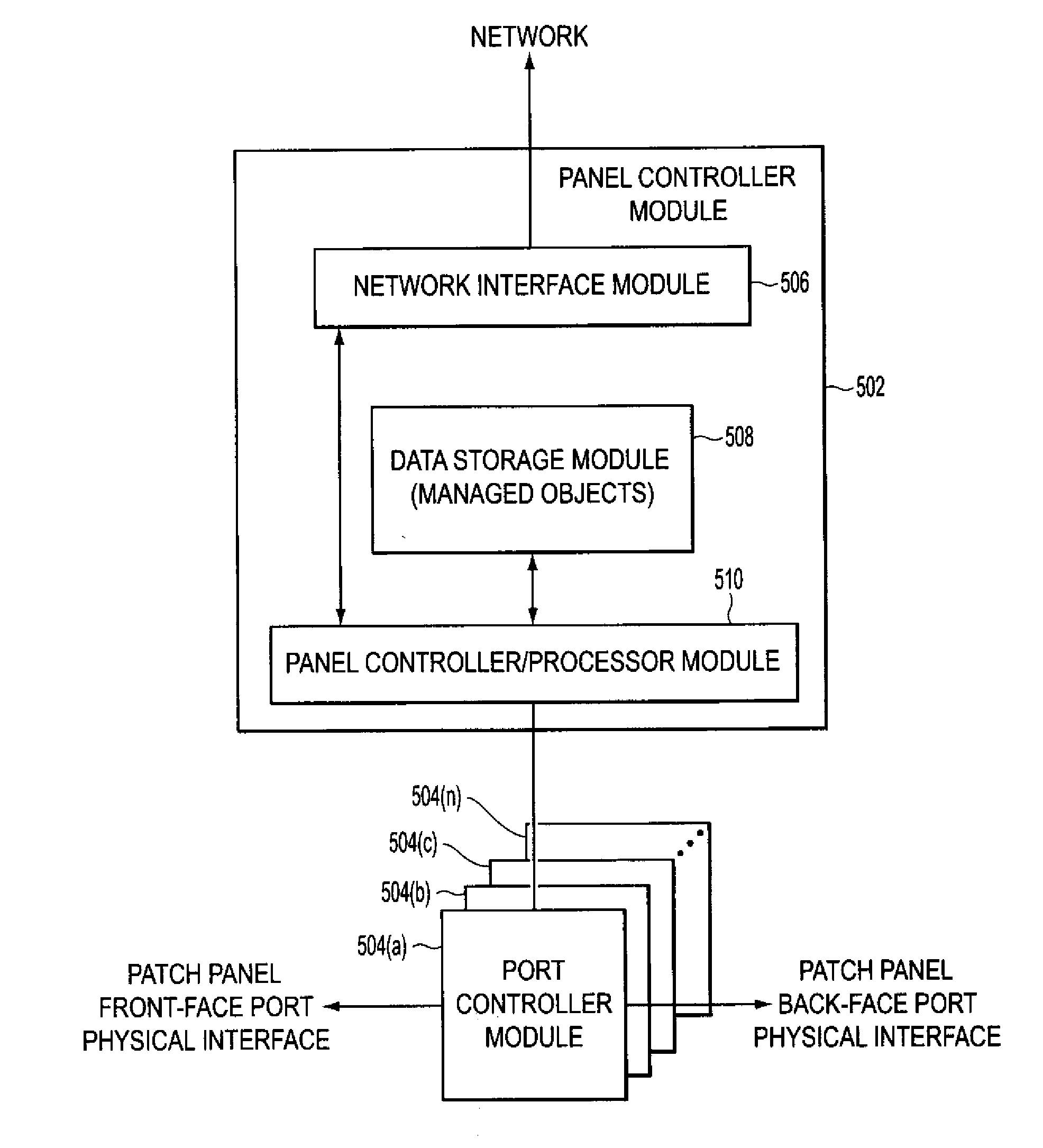
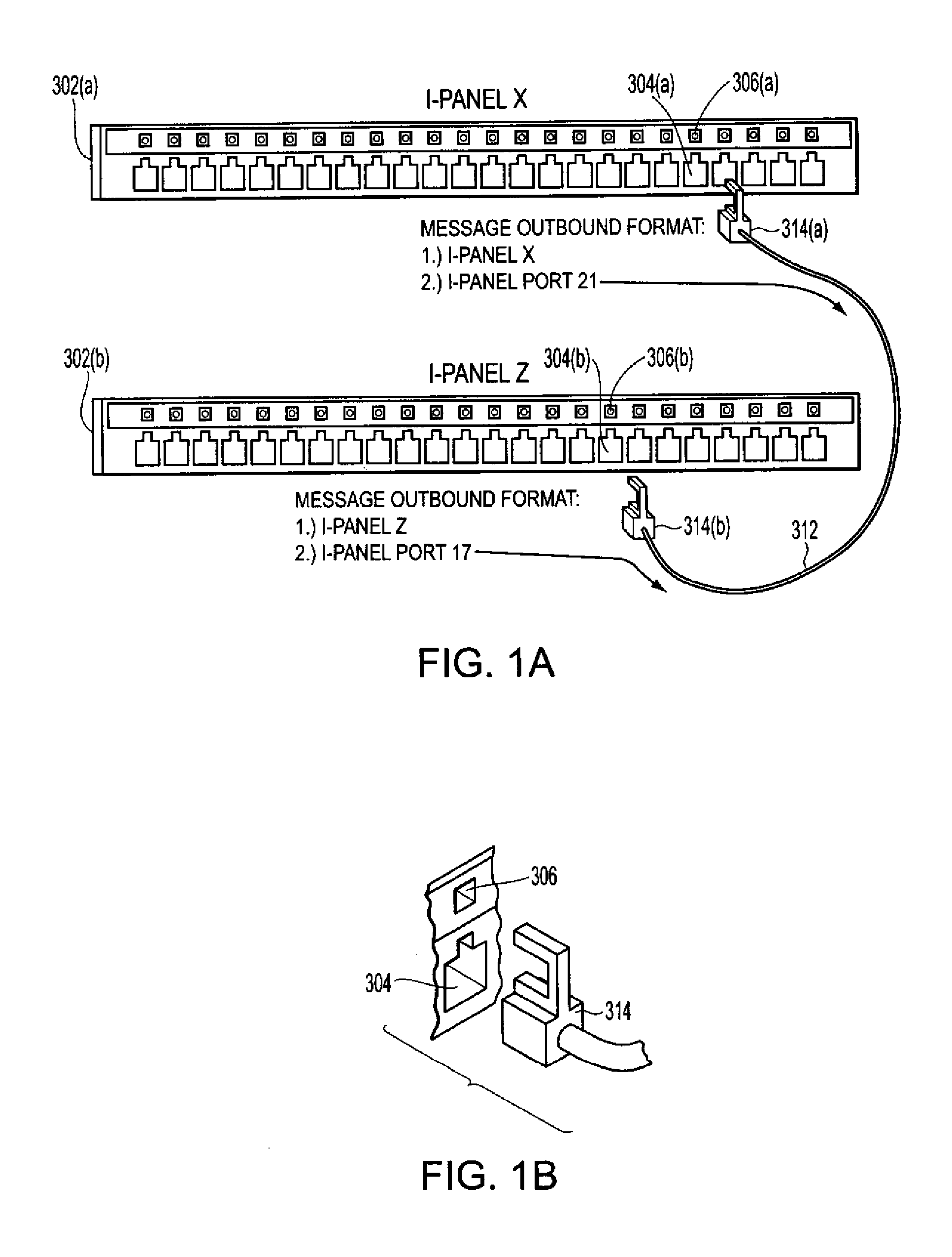
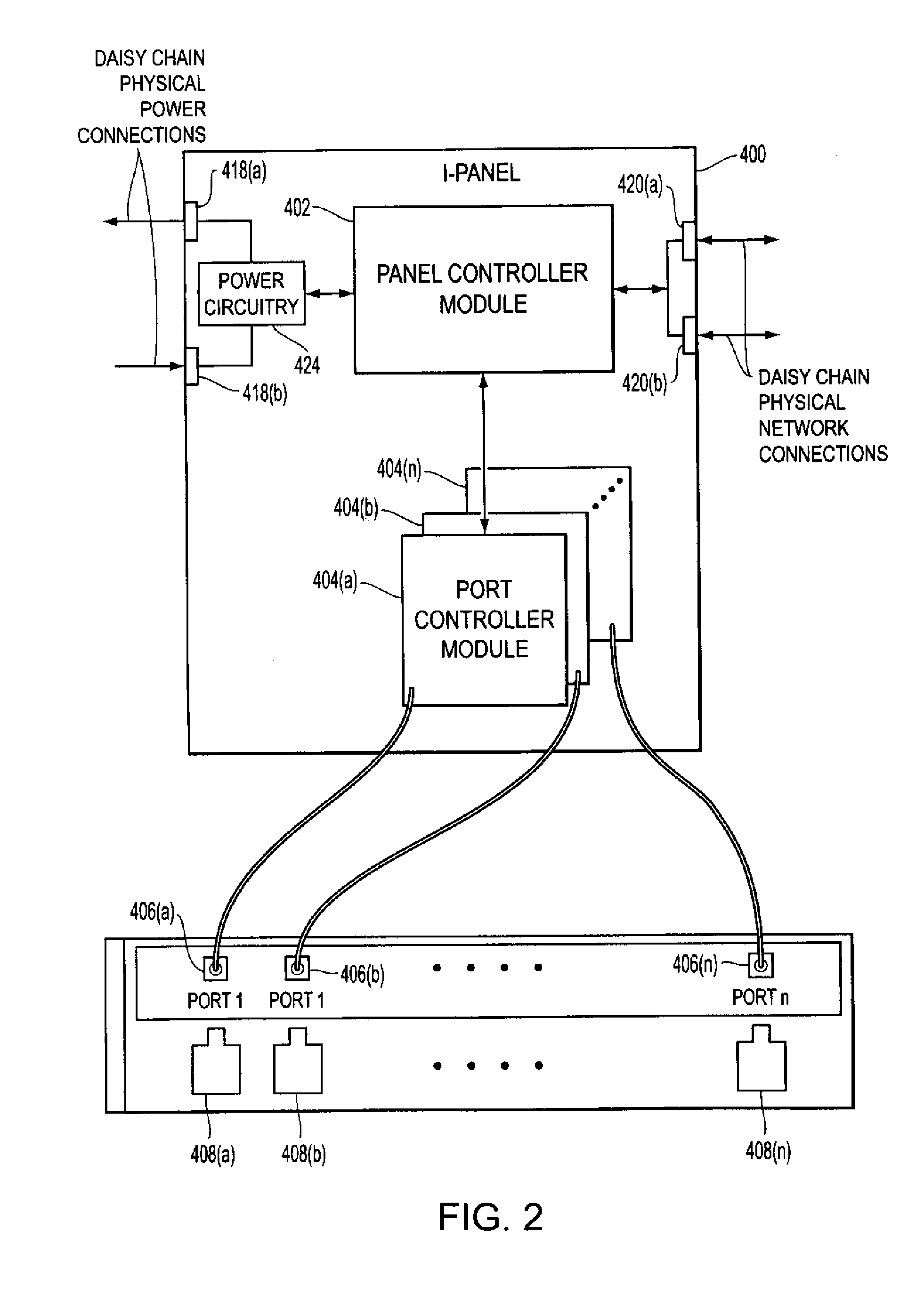
[0019] Methods and apparatus for monitoring the physical topology of a network may be applied on a real-time basis, and may be applied to a variety of network devices. For example, as described below, exemplary embodiments may be applied to monitoring the physical topology of a network based upon dynamically monitored patch panel connectivity.

[0020] Networks may be characterized by a logical topology and a physical topology. The logical topology of a network includes information related to the logical connectivity of devices connected to the network. For example, the logical topology for a data or telecommunications network may indicate the presence and identity of network devices (e.g., routers, switches, intelligent hubs, etc.) connected to the network, the presence and connectivity of end-user devices (e.g., servers, network data repositories, printers, user workstations, etc.), the logical connectivity (e.g., logical ports that are enabled on each of the respective devices for ...


PUM


Abstract

A method and apparatus are provided for monitoring the physical topology of a network on a real-time basis. For patch panel systems, the approach is based upon a distributed architecture that may be modularly scalable and may allow each patch panel to determine port level connectivity by independently monitoring an out-of-band channel supported by each respective port. The approach provides improved real-time reporting of patch panel connectivity with reduced cabling complexity, increased reliability and decreased maintenance costs. The approach is capable of determining the physical equipment and/or physical location information associated with the respective patch panel ports, in real-time, and thereby provide physical network topology information associated with patch cord connections. The approach is compatible with multipurpose network management systems.

Description

CROSS-REFERENCE TO RELATED APPLICATIONS [0001] This application claims the benefit of priority under 35 U.S.C. §120 to U.S. Provisional Patent Application No. 60 / 690,149, filed on Jun. 14, 2005. This application also incorporates by reference U.S. patent application Ser. No. 11 / 265,316, entitled “Method and Apparatus for Patch Panel Patch Cord Documentation and Revision,” filed on Nov. 2, 2005, which claims priority to U.S. Provisional Patent Application No. 60 / 624,753, filed on Nov. 3, 2004, and U.S. Provisional Patent Application No. 60 / 690,150, entitled “Method and Apparatus for Reliable Network Cable Connectivity,” filed on Jun. 14, 2005, in their entirety.BACKGROUND [0002] 1. Field of Invention [0003] The present invention pertains to network cable management. [0004] 2. Description of Related Art [0005] One exemplary approach for collecting physical network topology information has been to replace traditional passive network cable systems with systems that support rudimentary s...

Claims


Application Information

Patent Timeline
Patent Type & Authority Applications(United States)
IPC IPC(8): G06F15/173
CPCH04L43/0811H04L41/12H04L41/344
Inventor NORDIN, RONALD A.
Owner PANDUIT
Why Eureka
Try Eureka